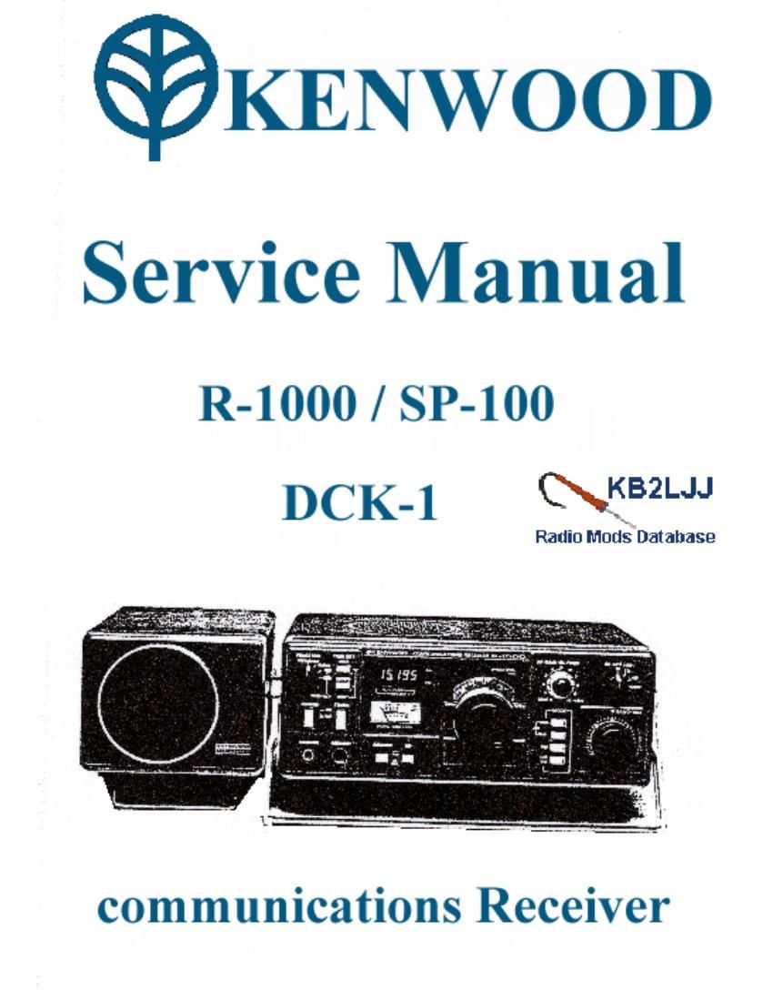
Kenwood R 1000 Service Manual

This is the 32 pages manual for Kenwood R 1000 Service Manual.
Read or download the pdf for free. If you want to contribute, please mail your pdfs to info@audioservicemanuals.com.

Page: 1 / 32
left right
Kenwood R 1000 Service Manual

Extracted text from Kenwood R 1000 Service Manual (Ocr-read)


Page 3

CIRCUIT DESCRIPTION

R-1000
RECEIVER CIRCUIT CONFIGURATION

The R-IOOO has [W0 dtfferent antennas one for 0 ~ 2 MHz
ltmpedance l k9) and the other for 2 ~ 30 MHz (Imped-
ance I kl) and 50m The Input stgnal from the antenna ts
coupled to a vartable attenuator covertng O to -60 dB tn 20
(18 steps Thts attenuator ts provtded Ior each antenna The
stgnal then goes to bandpass ftlters covertng stx bands. 0 2
~IMHz.I~2MH2,2~4MH2.4~8MHZ.8~I6
MHz. and 16 ~ 30 MHZ Alter passmg through the band-
pass ftlter, the stgnal ts fed to RF ampltfter OI (MOS FET
3SK74ILI), then to a 48055 MHz lF trap The stgnal (cover-
trtg a frequency range from 200 kHz to 30 MHz) ts then led
to amplttters 01 and 02 (28K125l where tt ts ampltfted by
approx 15 dB, It then goes through a wtde-band
transformer before betng fed to a balanced mtxer con5tsttng
of two 3SK74, where tt ts mtxed wrth the VCO stgnal fromthe
PLL Ctrcutt to be converted tnto the 48055 MHz Ist IF
stgnal The Ist IF stage consrsts of monoltthtcftlters MCF FI
and F2, The lst IF 5tgnal ts then led to the 2nd mtxer con-
srsttng of 05 and 06 (3SK74X 2), where tt IS mtxed thh
anmher local frequency of 476 MHz to be converted tnto the
455 kHz 2nd IF StgnaI, After passmg through an NB gate.
the 2nd IF signal goes to ceramtc Itlters F5. F4, and F3 each
dedtcated to 588. AM N, and AMW respecttvely. The stgnal
then goes to IF ampltfter O7 and 09 I3SK74 x Zl before it
branches tnto the AM detector and $88 detector, The detec-
tor output ts ampltfted by ampltlter 027 (2802240) to
provtde the RECORD output At the same ttrne. the ampltfter
output goes through the TONE and GAIN controls before It ts
power ampltfted by 028 (HA1368FI) to drtve the
loudspeakers

thlerent AGC ttme constants are automattcally selected for ,

CIRCUIT DESCRIPTION

PLL CIRCUIT

The PLL Ctrcutt conltguratton is shown in thure 1

The PLL CIrCutt tn the R~IOOO Conststs of 4 VCOs covertng 0
~ 7 MH2,8~ 15MH2.16 ~ 22 MHz,and23 ~29MH2
to osctllate on 48 055 ~ 78 055 MHz (07-10:
25C1923(O))

The VFO and 01 (28Cl923l0ll oscrllates tn combtnatton at
a frequency ol 476 MHz, whtch ts coupled to a buffer
l2$C460lB)l then ts mtxed down by ICl (SNISQIBP) to
42 055 ~ 43055 MHZ Thts stgnal ts coupled to |C3
(5N16913P). where tt ts mtxed wtth the VCO frequency
I48 055 ~ 78.055 MHzl to be converted tnto a Stgnal from
6 to 35 MHz Thts ts then ampltfted by a 20 dB ampltfter
conststtng of 015 ~ 018 vta bandpass filters T9 ~ T12,
The amplttter output ts frequency-dwtded tnto I MHz by
programmable dtvtder |C4 ~ |C7 The IMHz dtvtder output
18 then subtect to phase compartson by ICE (MC4044P)
whtch constttutes the PLL loop The frequency-dtvtdtng
5tgnal. band swttchtng stgnal. and VCO swttchtng signal are
all created by the BAND swttcht The mtxer output IC2
ISN169I3PJ, whtch mtxes the VCO frequencnes (48.055 ~
78055 MHzl wtth 47 6 MHz has the frequency of the
reserved Stgnal frequency plus 455 kHz, Thts Stgnal ts coupl-
ed to the RX untt vta the CON termtnal to be used as the
counter output.

888 and AM.
RX unlt
PLL UNIT XSO-IGIO-OO lst MIX
[-_--____-_'___- ___-_'"'-"__-""I
I
msurr on use WW 5,,
e ® tr :
Rx untt
otvtoen tcs BUFF 029
35.0. s~ If; t
tut)? I "
, o .0 EL'Z I/

15c
CW Instztx:


:0ch
tensxt DIVIDER

SWMIY ICIa
WW .
94145le SMSDON
W

Intern.-

: M»

L___-_- __________

3 v ozot
m AVR

ISCIIISIVI-
zsuntvt

surr m: ID
0:

Irv tzv

mm

on: us M. mtg:
Isctsss

250mm m

____________. _I
FtomVFOuni\

To power transformer

Fig. 1 PLL unit block diagram

Page 28

SP-IDO

SP-100 SPECIFICATIONS

Speaker Size:

Hated Input
Impedance:
Frequency Response:
Dimensions:

10 cm

1,5W

89

200 Hz ~ 10 kHz

149 (WIX 115 (HIX 211 (D) mm
57/8 (W)X4»1/2 (HlX8»15/16 (D) inch

Weight: Approx. 15 kg 133 lbs)
SP-100 PARTS LIST
G E N E R A L
Ref. No. Pans No, Description 9'
marks
- A01-0765-02 Case Y}
- A20~2373«15 Panel w
- 804-0402-04 SP net 1?
- 307-0622-04 SP ling {Fr
- 843-0632-04 Name plate IT) a
- ' 843-0633-04 Name plate (K) w
- 339-0407-04 Spacer
- 653050904 Packing
- 653-0508-04 Packing
- 850-2695-00 Operating manual [K] 11'
- 550-2698-00 Operarinvg manual (T) i!
- E20-O2OB-O4 Terminal plate
- E30v1629-05 SP Cord
- J02-0323-05 Foot
- J02-0417»04 Assistant fool {z
- J21»2573-04 Fours mounung metal
- J61-0019«05 Vinylene
- TO 7-0207-05 Speaker 3}
- H01-2660-04 Carton (K) {7
- HOI-2661-04 Canon (T) i?
- H10-2526-02 Right Side packing Iixrure
- H10»2527-02 Left sude packing fixture
- H20-1407~03 PIOIECUVS Cover
- H2S»OO77-O3 PIOIECIIVE bag
D C K- 1
DC COR D KIT PARTS LIST
OPTION (K)(W)(T)
i
Rel. Nol Pans No. Description Re'
marks
- 350-2703-00 Operating manual x}
- EDS-020345 2F Connector
- E3 I ~2027~05 Cable with rerminal
- Elm-154605 DC cord ASSY
- 505-1023-05 Fuse UL IAXZ
- H25-0029-04 Protecriva bag 60mm X 1 10mm
- H25-0117-04 Protective bag 80mm X 250mm