Kenwood MX 5000 Service Manual

This is the 10 pages manual for Kenwood MX 5000 Service Manual.
Read or download the pdf for free. If you want to contribute, please mail your pdfs to info@audioservicemanuals.com.

Page: 1 / 10
left right
Kenwood MX 5000 Service Manual

Extracted text from Kenwood MX 5000 Service Manual (Ocr-read)


Page 1

r\

\/

KMF7X9000(K)INT1P 01.10.115:12PM «HAS/1

STEREO POWER AMPLIFIER

KM F-X9000/X9000-S

MX-5000

SERVICE MANUAL

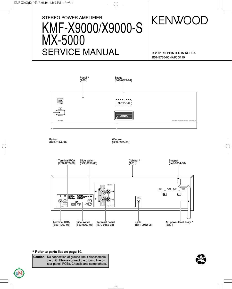
Panel * Badge
(A60-) (843-0322-04)

KENWOOD

©2001-10 PRINTED IN KOREA
351-5760-00 (K/K) 3119

Button
(K29-8144-08)

Terminal RCA

Window
(303-3905-08)

Slide switch

Cabinet * Stopper
(E63-1263-08) (862-0099-08) (AOL) (J42-0354-08)
l

'1' 54%» m'lilmaimx .-

ng Wm

ALT a a T

Terminal FICA Slide switch Terminal board Jack
(E63- 1262- 08) ($62- 0069 08) (E70-0162-08)

* Refer to parts list on page 10.

Caution : No connection of ground line if disassemble
the unit. Please connect the ground line on
rear panel, PCBs, Chassis and some others.

(E11-0952-08)

AC power Cord ass'y *
(E30-)

Page 2

KMEXQOOOGQINTIP01.10.115:12PM «um +
KM F-X9000/MX-5000

CONTENTS / ACCESSORIES


Contents
CONTENTS / ACCESSORIES .................................. 2 EXPLODED VIEW ...................................................... 9
ADJUSTMENT... ..... 2 PARTS LIST ............................. 10
PC BOARD ........ .3 SPECIFICATIONS ...Back cover
SCHEMATIC DIAGRAM. .. 7
Accessories
Audio cord (1) Stereo mini-plug cord (1) Speaker terminal cover (1)
(E30-0505-05) (E30-2733-05) (A09-1247-08)
/\
x 2
INPUT OUTPUT AMPLIFIER ALIGNMENT
No. ITEM SETTINGS SETTINGS SETTINGS POINT ALIGN FOR FIG"
Unless otherwise specified, the individual switches should be set as following:
POWER: ON
Connect a DC voltmeter
between pin 1 and pin 2
1 IDLE CURRENT - of connectors. No signal input \IIIRIggIlRI) 20 mV

CN107 (Lch)
CN106(Rch)