Kenwood LDK 300 V Service Manual

This is the 29 pages manual for Kenwood LDK 300 V Service Manual.
Read or download the pdf for free. If you want to contribute, please mail your pdfs to info@audioservicemanuals.com.

Page: 1 / 29
left right
Kenwood LDK 300 V Service Manual

Extracted text from Kenwood LDK 300 V Service Manual (Ocr-read)


Page 1

LDeKBOOVUO COVER( 98.4 .23 8:58PM y [W 2 gr

LD-K3OOV KENWOOD

SERVICE MANUAL

© 1997-8/851-5333-00 (K) 2337

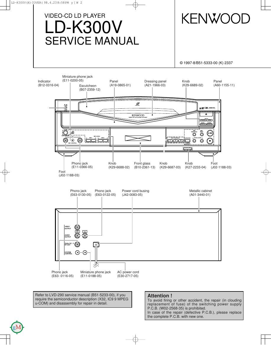
Miniature phone jack
Indicator (E11'0200'05) Panel Dressing panel Knob Panel
(812-0316-04) Escumheon (A19-0865-01) (A21 -1 966-03) (K29-6689-02) (A80-1155-11)

(807-2359-12)

L'

Phono jack Knob Front glass Knob Knob Foot
(E11-0366-05) (K29-6688-02) (B10-2361-13) (K29-6687-03) (K27-2233-04) (J02-1188-03)
x \ Foot
(J02-1188-03)
Phono jack Phono jack Power cord busing Metallic cabinet
(E63-O130-05) (E63-0122-05) (J42-0083-05) (A01 {3440-01)
3

mm @
.m 6 fl
0mm / w

22:11 @
n
:m 67v

m

Phono jack Miniature phone jack AC power cord
(E63- 0116-05) (E11-O188-05) (E30-2717-05)

Refer to LVD-290 service manual (851»5233-00), if you Attention !

require the semiconductordescnption (X323 [09 9 MPEG To avoid firing or other accident, the repair (in clouding
U'COM) and disassembly for repair In detail. replacement of fuse) of the switching power supply
P.C.B. (W02-2568-35) is prohibited.

In case of the repair (defective P.C.B.), please replace
the complete P.C.B. with new one.

Page 2

LDEKBOOVfK) COVER( 98.4 .23 8:58PM y [W 3 gr

LD-K3OOV

CONTENTS / ACCESSORIES / CAUTIONS

Contents
CONTENTS / ACCESSORIES / CAUTIONS .............. 2 EXPLODED VIEW .................................................... 26
ADJUSTMENT .3 PARTS LIST .................... .28
PC BOARD .5 PARTS DESCRIPTIONS .37
SCHEMATIC DIAGRAM ............................................. 9 SPECIFICATIONS ...................................... Back cover
Accessofles
Audio cord (2) Video cord (1) System control cord (1) AC plug adaptor (1)
(E30-0505-05) (E30-1427-05) (E30-2733-05) (E03-0115-05)

Use to adapt the power cord to
the shape of the wall outlet.
(Accessory only for regions
where use is necessary.)

Cautions

Beware of condensation

When water vapor comes into contact with the surface of cold
material, water drops are produced. lf condensation occurs, correct
operation may not be possible, or the unit may not function correct-
ly. This is not a malfunction, however, and the unit should be dried.
(To do this, turn the POWER switch ON and leave the unit for sev-
eral hours.)

Be especially careful in the following conditions:

0 When the unit is brought lrom a cold place to a warm place,
and there is a large temperature difference.

0 When a heater starts operating.

0 When the unit is brought from an air-conditioned place to a
place of high temperature with high humidity.

0 When there is a large difference between the internal tempera-
ture of the unit and the ambient temperature. or in conditions
where condensation occurs easily.

Nole related to transportation and movement

Before transporting or moving this unit, carry out the following
operations.

1. Turn the power ON but do not load a disc.

2. Verify that the display shown appears.

3. Wait a few seconds and turn the power OFF.

Page 3

LDTK3OOV(K)1P 98.4.248128AM y [W 1

MAIN UNIT(X34-1033)

4%

ADJUSTMENT

LD-K3OOV

No ITEM INPUT OUTPUT PLAYER ALIGNMENT ALIGN FIG
' SETTING SETTING SE'I'I'ING POINT FOR
Frame No.19,001
Connect the STILL (Still image) Minimize the
TV monitor to the crosstalk on the
TILT video output. Frame No.23.402 screen.
1 BALANCE LD TEST DISC STILL (still image) VR3
Connect an .
. , Frame No.20.000 Eye-pattern ls
°Efig§f£gié$5l§ ' STILL (still image) maximum and clear. (a)
FOCUS Connect an Maximize the RF
2 TEST DISC oscilloscope to RF : PLAY VR2 signal (eye pattern) (a)
BALANCE . .
CNS pin 6 (EFM). amplitude.
Setting the TEST MODE (Short-circuiting the CN7 pin 1 and 2 in AC IN mode : TE OFF)
Connect an
TRACKING - Symmetry between
3 BALANCE TEST DISC géclllglslgogieqto TE OFF VR1 upper and lower. (b)
Connect an L.P.F.to
TEST DISC -
4 FOCUS Apply a signal Cwfilgl'lngohfigglinw PLAY VR4 Two VTVMs should
GAIN (éfingzégizpq-ggo oscilloscope or two read the same level.
p ' AC voltmeters.
Connect an L.P.F.to
TEST DISC -
5 TRACKING Apply a signal CWElEl'lfonfiQSlinw PLAY VR5 Two VTVMs should
GAIN (CNEHZintiztvajnggo oscilloscope or two read the same level.
p AC voltmeters.
Terminate the video SFrame No.100
output with a 759 TlLL(still image) » -
6 Ellie/TEE LD TEST DISC resistor and connect VR7 am Ii/tlgggtflgtnSI/ _
an oscilloscope to *Frame No.13.000 p ' p p
both ends. STILL(sti|| image)
Connect a
7 4Fsc POWER ON 'éfiéflETSIdcfiElfiré? STOP TC1 14.31818MHzi50Hz
|C3 pin 7.
VIDEO CD UNIT (X35-2170-20) Setting the power on
Connect a
frequency counter to
8 VEECECED POWER ON check land STOP TC1 13.5MHzt50Hz
(135MHz) ot
|C2 pin 99(R16).

Note : L.P.F. :33kQ+1000pF or so, CD disc : CD test disc (SONY YEDS-18 or equivalent), LD disc : CAV300m
(with digital sound), STILL : Remote controller's key.
fig. : Waveform (P.12)