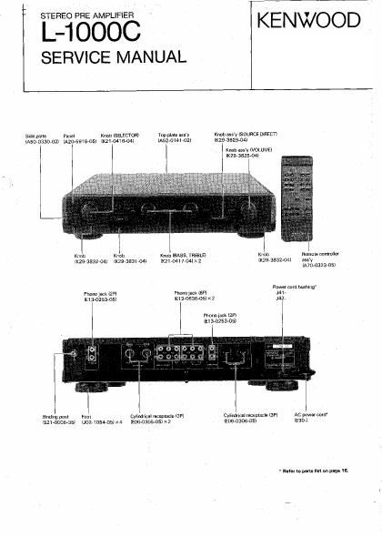
Kenwood L 1000 C Service Manual

This is the 18 pages manual for Kenwood L 1000 C Service Manual.
Read or download the pdf for free. If you want to contribute, please mail your pdfs to info@audioservicemanuals.com.

Page: 1 / 18
left right
Kenwood L 1000 C Service Manual

Extracted text from Kenwood L 1000 C Service Manual (Ocr-read)


Page 2

Lllddoc

1.

CIRCUIT DESCRIPTION

Sal-nee Ea oi un

Cannemwo E0 amps (may ma same cimuh)

as shown In me nouns VIM! regard to me COLD

slda Input. connect ms HOT side NF resbunae

to me COLD slda inverslon lnpm.

The HOT side cosmos in the same manna! as

in me 056 OI "I9 conventional EQ circuit.

When he HOT Side is operated, gale 07 is

oonnsmso vlmlally.

Wllh ysgard In the COLD smei voltage, WhIOh l5

applied to gate 05 is appllea in me inversion

input

Tne chamcrevsflcs oi this amp gain is ablained
ZIRIAA)

GAIN=1 r?

. Balance volume Clwuil

This Dre amp employs a balance volume clmuil
in and'niun. oy oomoinlno wllh vavlahle and GAIN
AMP n lmpwvas SIN.

when this we amp is Opsmllng or when VHMIN
the NF [894me becomes B maximum DI 5.1K
and me gain is also reduced ante same «me as
inoul ls reouosd

316K x 2

GAIN wnen VRMA: K
s s,7llnias(la ads)

31 SK X 2
61K
: ziimes(6.fldE|

When WWIIN =1

. aahnoem Unoalxnoo conversion Amp

This amp convens ms signal Xransmmsd a:
balance in ma unbalance signal. I! negales
external noise slgnals ganavmed ln phase aI mo
HOT and com sass. and anions me ossned
signal Duly

In this per amp, the oonslanz has been sol m
ubLain oumul valmge, which is In mat 01 mo lnpm
voltage between HOT ano GOLD

H I

GNN-Trzarz
where R,:2R2 ls seq

(W o

n2

av

/
\

Page 3

( 4.

c

CIRCUIT DESCRIPTION

Unbalanee to aalanos Conversion Amp

in this amp the unbalance signal, which is input
at the RCA pin. etc.. is applied to the
noninverting input ot the A side amp. As the
output and inversion input are directtv connected
in this amp. it operates as a GAIN:T buIIei amp.
and outputs gnai to posrtive phase won.

a side amp grounds noniverting input, and
operates as a inversion arm: in which NF
resistance is set to the same value (Rem)

When A amp (positive phase) output is input.
lhen the negative-phase output (COLD), which is
an inverted phase. is output.

The output voitage oi this circuit (belween HOT
and cowl is Mine as large as the input voltage

Microcomputer Port
TDTHCZSIRP

This microcomputer pail mansion IC is In ufilize
the microoomputer port eilectively The
mlcmcompulei OUIDLII signal, which is Encoded
lo 3 bits. is decoded to six relay controi signals

Extension Ic

input output
a v. v, v. v. vi v.

Ewan:
9

All the signals are L besides H.

V; 7mm)?»

Av


L-1000C

L-1000C

CIRCUIT DESCRIPTION

Fre Amp Unii (xos- -2362- -70)
. Ea Circuit 0P Amplitier (lot a)

Two sets ol Eo ciruits are used per 16H as this
OF ampiiiier has baiance E0. The HOT side
(noninvemng amplllier) is a conventional Eu
circuit. and the COLD side (inverting amplifier)
receives an NF lleed hack] signal oi the HOT
side which is added to the inverlin put By
doing so, the inverted output can be obtained

2. Raisnce input Circuit antler Amp (ica. 4)
This becomes an impedance conversion buiier
ampwhen gainist

a. LINEI input Circuit Amp (le, s)

This converts the unbalance signal [me signal
which is connected by an RCA pin) to the
balance signal. This also Sewfi as an input
bulleramp,

4. LINE 2 Input Circuit Ampiiiier (i121. s)

This converts the unbalance signal (the signal
which is connected by the RCA pin) to the
balance sipnai This also serves as an input
butter amplifier.

5. TAPE t lnputCircuitAmpliliaraCtl, 10)

This converts the unbalance signal (this signal
which is connected by lhe FICA pin) to the
balance signal. This also serva as an input
butter amplifier.

is. TAPE 2 input circuit Ampliller (lCtl, t2)

This converts the unbalance signal (the signal
which is connected by the RCA pin) to the
balance signal This also serves as an input
butter amplitier

7. Balance-unbalance Conversion Amplitier

("212)

This is a conversion amp to output the balance

input signal to the REC OUT Circuit lunbplance

signal). and the gain is setto soda

REC ouT selector analog SWs (isz-zs)

. BalanCo-Unhalailoe Conversion Amp (lczs)
This balanceaunbaiance conversion amp is to
output the pre amp output. which is transmitted
at balance. to apparatus which has only
unbelanoe input. and the gain is setto 7 MB.

to. Power iC ior Relay and Motor Iv 029)

The maker or this VR power lc is limited to

correspond with 15v three terminal tone duanuty
ti. Power is tor Relay and Motor iv (icani

The makav ot this VR power lC is limited to

correspond with i2v three terrninai tone quantity

09°

2. Negative side Power First OFF Circuit (ms,
044)
This is provided to reduce the power supplied to
each section. especially to reduce the electric
potential oi the EQ circuit to a leed value. when
power is OFF.

13. Analog sw Control Signal Generation Digital
Transformer ior REC oiJT Clmuk (on-52)
This convene the level oi ovi iDPEN to a 15v
i mov

to. Relay DriverTranslslor (053-55)

This drive relays lrcm the microcomputer output
signal.

15. Zenor niode lor Relay circuit (ma, 047-53)
This shabiiizes the surge killer and control
signals

ts. REC ouT sw Diode 035255)

This generates the SOURCE signal

Tone Uni (X11-2302-70)
1. OP Amp lor Lcii Line Amp (le)
This serves as both the volume butter amp and
the balance output amp.
2. OP Amp tor Rct-l Line Amp 02)
T serves as both the volume butler amp and
the baiance oinoui amp.
3. Tone Output Buflar 0? Amp «in;
This serves as an unbalance id baience the
conversion output amp oi the tone circuit.
4. input Conversion OP Amp lor Tone circuit
(ion)
This is a oeianceunbaiance conversion amp lor
the tone Circuit.
5. u CON Circuit Reguia r it: (I017)
This is a 5v threerteimiilal regulator iC tor u
CON uit
e. Transistor Array (iczt. 22)
These are seven element transistor arrays
7. Power Relay Drive Translstor(017)
This drives the relay by the miclocomptfler
signal
a. Constant-Current Diode (Du-32)
This drives a relay drive circuil al a constant
current,
a. Rotary Detector (so)
This is lor the source selector and reselector.
to. ceramic Resonator on)
This is a microcomputer clock oscillation element
(GDDKH,)