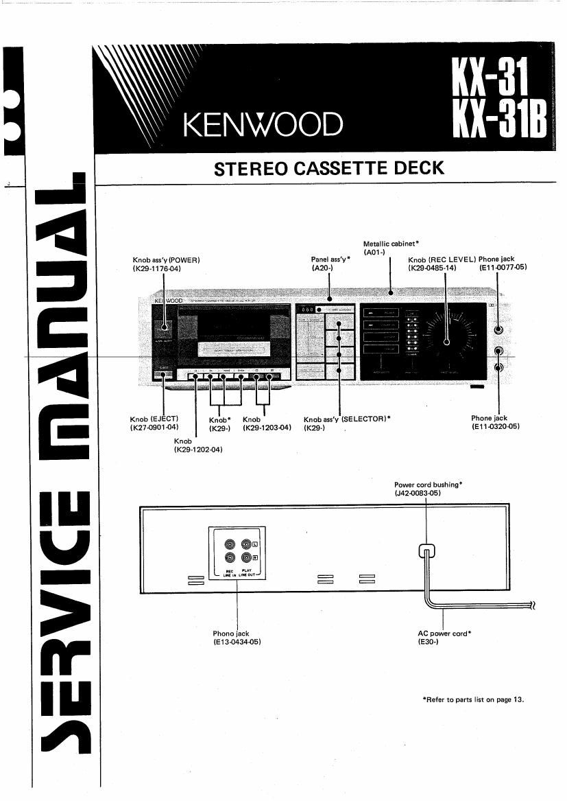
Kenwood KX 31 B Service Manual

This is the 29 pages manual for Kenwood KX 31 B Service Manual.
Read or download the pdf for free. If you want to contribute, please mail your pdfs to info@audioservicemanuals.com.

Page: 1 / 29
left right
Kenwood KX 31 B Service Manual

Extracted text from Kenwood KX 31 B Service Manual (Ocr-read)


Page 2

IlX-3ll31ll

ADJUSTMENT

1 Notes for Adjustments .
a) Load resistance: A pure resistance load of. 100 k9

, should be connected to the LINE OUTPUT terminal.
bl Standard level: 0 dE§s=O.775 V

c) The electrical system should be adjusted by dividing it

into playback and recording.

Adjustment of recording requires perfect performance
of the playback system.

No special adjustment should be required unless inner
components are replaced.

When the head is replaced, its stray magnetism must
be completely erased by the demagnetizer prior to
mounting the tape.

Unless otherwise designated, measurement shomd be
carried out with the Dolby NR switch off,

d

9

Test Instruments. Tools and Jigs

OAC voltmeter (High input impedance)

OAUdio signal generator: AG

IOscilloscope

' l-requency counter

'Wow and flutter meter

OWeighting filter
(ASA A characteristic with NAB curve)

~Band pass filter lCenter frequency: 125 H2, 1 kHz;
Attenuation: 18 dBloct. or more)

OCassette type torque gage lTWle l l: T99-0208-00l

OSpring balance

UTorque dial

'Head demagnetizer

OCIeaning tape (T93-0014-05)

5Mirror tape lT93-0021-00l

Test Tapes

al Test tapes for recording section adjustment
Normal: KENWOOD ND-BO, TDK AD C-BO
CrOz: KENWOOD CD-60, TDK SA (2-60
Metal: KENWOOD MD-60, TDK MA 060

TEST TAPE SPECIFICATIONS

b) Test tapes for playback section adjustment
Tape speed and wow and flutter:
TEAC MTT-l l l lT93OOl 5-00)
Frequency characteristic and azimuth:
TEAC MTT-256 (T93-0025-OO)

4 Meaning at Technical words
a) Standard playback condition: The state obtained by
reproducing the reference level 315 Hz signal (160
pr/mm) of the test tape and by adjusting the
playback level so that the standard output level
l-9st = 0.275 V) can be obtained at the LlNE
OUTPUT terminal.

b) Standard recording condition: The state obtained by
applying the 1 kHz signal to the LINE lNPUT jack at the
normal input level (-10 stl and by adjusting the
RECORD LEVEL volume control so that recording can
be carried out at the normal recording leveli
Standard recording level: A level to obtain residual

magnetic flux of 160 pr/mm on the standard record<
k' hie-RADHI inrthnl IQ1RH7ndR

C

ins ivy ,
(160 pr/mml of the test tape (MTT»2561.
Standard input level: The standard input level
necessary for obtaining the normal recording level. The
levels at respective input jacks are as specified below.
MIC ....................
LINE lNPUT ..........
el Standard output. level: The standard signal level
obtained at the LINE OUTPUT jack when the reference
level 3i 5 Hz signal is reproduced from the test tape.

d

MTT-256 31 5 Hz (160 pr/mm)
Output level: - 9 st
Note:

DOLBY and the double-D symbol are trademarks of
Dolby Laboratories Licensing Corporation.

Noise reduction circuit made under license from Dolby
Laboratories Licensing Corporation.

DESCRIPTION
MODEL TITLE TIME CONSTANT APPLICATION
FREQ/LEVEL PROGRAM
3 kHZ - IOdB 3W; Ta S d T
1 F m l:L . a pee 35
MTT 1 1 L 10 dB 30 Mm Wow and llutter Test
(Thickness l3 um)
31 5 Hz~ 1 4 kHz
OdBI-ZO dB :rs IOk 3L5 a: 150 u 4i 8k lzbk
MTT-256 FREQUENCY 3180 us and 0 dB=DIN Jsdgflsanis an 115 509 2r on lot in FREQUENCY Response
20 5 REFERENCE LEVEL 30:40qu Tes
- 4 dB

Page 24

Iill-lllll/31

MECHANISM DESCRIPTION

5. FF Operation (1)

(ll

(2)

l3)

(4)

The FF slider is pushed up (@l by pressing the FF button
l®l and the brake slider is pushed up by the FF slider.
l®l

Projection (f) of the FF slider pushes the FR lever and
rotate it in the direction shown by the arrow @. The FR
trigger lever then rotates in the direction shown by the ar-
row (5), pushed by the FR lever. '
Projection lg) of the FR trigger disengages from projec
tion lhl of the FR gear. (©)

The shift arm (B) is pulled by the FR trigger spring and

FR trigger spring
Pro], lg)
Proj. lhl

Shift arm (B) Vl

l6)

(7)

(8)

pushes the cam on the FR gear l®i to rotate the FR gear
slightly in the direction shown by the arrow .

The flywheel gear and the FR gear engage with each
other and the FR gear is rotated (®)

The FR gear stops when the non-toothed portion of the
FR gear meets the capstan gear,

The shift arm (Bl, pulled by the FR trigger spring, pushes
the cam on the FR gear ( ® l to rotate the FR gear
slightly in the direction shown by the arrow l 63 l
Projection (ii of the FR gear comes into contact with pro-
jection (g) of the FR trigger gear and the FR gear stops
rotating

Fig. 6 FF operation (1)

Rewind slider