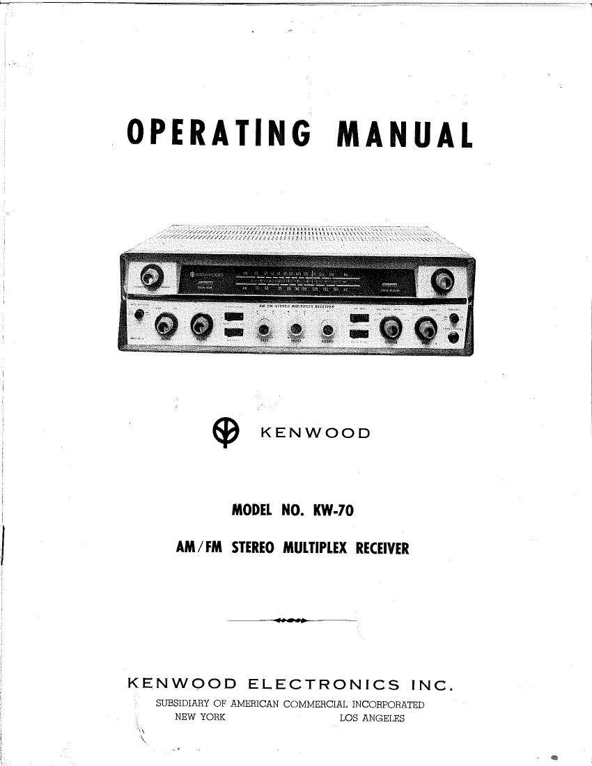
Kenwood KW 70 Owners Manual

This is the 9 pages manual for Kenwood KW 70 Owners Manual.
Read or download the pdf for free. If you want to contribute, please mail your pdfs to info@audioservicemanuals.com.

Page: 1 / 9
left right
Kenwood KW 70 Owners Manual

Extracted text from Kenwood KW 70 Owners Manual (Ocr-read)


Page 2

KENWOOD KW-70 AM/FM STEREO MULTIPLEX RECEIVER

KENWOOD KW-70 requires only a pair of
loudspeakers to reproduce the thrilling brilliance
of stereophonic sound. Built-in FM Stereo
multiplex circuits of latest design - featuring
KENWOODs exclusive Stereo Indicator - brings
you new simplicity and convenience in FM stereo
broadcast listening.

KENWOOD KW-70 also functions as a complete
preamplifier-control center with RIAA compen-

sated phono input for magnetic cartridge, plus an
input for crystal or ceramic cartridge, plus an
input for stereo tape recorder or other program
source. A convenient stereo headphone jack on
the front panel makes it easy to enjoy fine music
in complete privacy.

KENWOOD KW-70 has been designed under
KENWOODs rigid engineering requirements for
lasting quality and pleasure.

SPECIAL FEATURES OF KW-70

A) The KW-70 has a rated music power of 32.5
watts on each stereo channel or a total of 65
watts on monaural.

B) The FCC licensed built-in multiplex adapter
is provided for FM stereo broadcast.

C) Selection of'IFM stereo broadcast station is
simplified with the help of Stereo Indicator (beam
tube) located on the front panel. KENWOODs
Stereo Indicator system is an unique circuitry
which is not affected by external noise.

D) Noise Filter eliminating high frequency
noise is provided for noise-free reception of FM

stereo broadcast even in fringe areas.

E) Rumble Filter is provided to eliminate low
frequency noise.

F) Hum is entirely eliminated with DC filament
supply system adapted to the equalizer circuit.

G) A convenient stereo Headphone Jack on the
front panel provides listening pleasure in com-
plete privacy.

H) RF Amplifier and Ferrite Loopstick Antenna
for AM are both provided; thus extra AM antenna
is not required within metropolitan area.

CONNECTING LOUDSPEAKERS

The KW-70 has output terminals for connec-
tion to speaker system of 4, 8, or 16 ohm im-
pedance. Wherever'possible, it is recommended
that identical speakers be used. For indoor

installations, ordinary plastic-covered lamp card

can be used to connect speakers to the receiver,
and may be extended as far as 100 feet without
any significant power loss.

Connect the left~hand speaker leads to the
terminals designated LEFT SPEAKER and the
right speaker leads to RIGHT SPEAKER. Con-
nect the output lead (Blue) to correct impedance
terminals (4 ohms, 8 ohms, and 16 ohms).

Warning: Never operate the receiver without
first connecting a speaker to each channel output.

CONNECTING STEREO HEADPHONES

Simply plug the headphone into the jack pro-
vided and push the SPEAKER switch to OFF
position.

Caution: Never leave the SPEAKER switch

H2

in OFF position if headphone is not connected
to the jack, or in the ON position if speakers are
not connected. This may cause damage to the
output tube circuitry.

CONNECTING STEREO RECORD PLAYER

The two shielded cables from your stereo
record player should be terminated with RCA
type phono plugs To avoid loss in high frequen-
cy, cables should not exceed ten feet in length.

Low Level Phono Inputs: Inputs from a
magnetic or variable reluctance (constant velocity

CONNECTING

For Playback Tape Head (without amplifier):
Using shielded cables, connect heads to the input
jack marked TAPE HEAD. See diagram on
page 6.

For Tape Recorder with Pre-amplifier: Using
shielded cables. connect the input lead of the
tape unit to the jack marked TAPE REC and

type) cartridge should be connected to the jacks
designated MAG.

High Level Phono Inputs: Inputs from Con-
stant-Amplitude phono cartridges such as crystal
and ceramic types should be connected to the

jacks designated XTAL.

TAPE RECORDER

also connect the output lead of the tape unit
to the jack marked TAPE PLAY. See diagram
on page 6.

After completing the connections, push in the
TAPE MONITOR switch on the front panel to
PLAY and you can monitor the output sound
of the recorder at the same time the recording is
being made.

ELECTRICAL CONNECTIONS

POWER

Plug the AC line cord into an outlet furnishing
110 to 120 volts AC, 50 - 60 cps. The AC outlet
on the rear of KW-70 is used to supply power
to another component, such as a record player,
turntable, etc.

AM ANTENNA

The ferrite loopstick built into the KIN-'70
assures adequate reception of all local AM
stations. However, in fringe and high noise
areas and where surrounding metal objects inter-
fere with normal reception, 3. regular antenna
lead should be connected to the terminal designa-
ted AM.

Note: The ferrite loopstick is mounted on the
swivel bracket and to obtain maximum pickup,
the loopstick should be swung away from the
chassis.

FM ANTENNA

Two terminals are provided for connection to

a 300 ohm FM antenna as shown in the diagram
on page 6.

For good FM stereo reception, always use the
best antenna possible. In areas close to the
transmitter, a simple indoor dipole antenna may
suffice. It should be remembered, however, that
the pick-up of reflections (similar to ghosts on
TV) will result in poor stereo reception. These
reflections must therefore be reduced to a mini-
mum, either by careful orientation of the indoor
antenna or, if this will not eliminate them, by
using a more directional outdoor type.

In areas further from the transmitter, the use
of an outdoor antenna in highly recommended.
These are available in various types. For recep-
tion of stations scattered in many directions, a
non-directional type may be required. If the
desired stations lie mostly in one direction, a
highly directional type of antenna will provide
better results. When using a directional antenna,
always orient it for best reception of the desired
station.

_3_