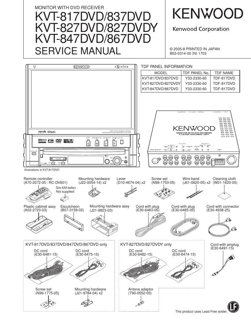
Kenwood KVT 817 DVD Service Manual

This is the 116 pages manual for Kenwood KVT 817 DVD Service Manual.
Read or download the pdf for free. If you want to contribute, please mail your pdfs to info@audioservicemanuals.com.

Page: 1 / 116
left right
Kenwood KVT 817 DVD Service Manual

Extracted text from Kenwood KVT 817 DVD Service Manual (Ocr-read)


Page 2

KVT-817DVD/827DVD/827DVDY
KVT-837DVD/847DVD/867DVD

NOTES ON ASSEMBLING THE MECHANISM

1. Fasten Screw A so that the interval (a) will be about 5.2mm
and the interval (b) will be about 2.6mm (The interval (a)
can be measured using a pair of vernier calipers or similar
tools.)

2. Turn B so that Position (0) will come at about the center of
interval (d).

3. Then, play the test disc and fine tune A or B so that the jitter
value would be minimized.

Page 40

KVT-817DVD/827DVD/827DVDY
KVT-837DVD/847DVD/867DVD

4o

ADJUSTMENT

O Adjustment item

1.

Chroma IC adjustment (X14)
(A remote controller is used for adjustment, while confirm-
ing on the waveform with an oscilloscope.)

. Freerun adjustment (X35)

(A variable resistor is used for adjustment while confirming
on the waveform with an oscilloscope.)

. Flicker adjustment

(A remote controller is used for adjustment, while confirm-
ing on the waveform with an oscilloscope.)

. Screen position adjustment

(A touch panel is used for adjustment. while confirming the
screen.)

. Touch Panel Adjustment

(A touch panel is used for adjustment.)

1. Chroma IC Adjustment Procedure (X14)

1.

While pressing on the [ATT] + [SRC] keys on the unit. reset
to enter the Test Mode.

. Press [DIRECT] key on the TV remote controller to get into

the Chroma IC Adjustment mode.
-> At this point CH :16 VCOiFREERUN VAL 80 is dis-
played on upper left corner. (VAL value is displayed in HEX.)

. Perform adjustments in Tables A~M in the order of a~c, one

by one.

a. Use [8] and [0] 0f 10Key to change the setting value. ->
The values in the VAL on the upper left corner of screen.

b. Press [PLAY/PAUSE] key to confirm the setting values.
-> When confirmed, the color of CH :16 VCOVFREERUN
VAL 80 changes.
Press [PLAY/PAUSE] key once more to release.

c. Use [7] and [9] of 10Key to move to the next setting. ->
The CH value in the upper left corner of screen changes.

. Press [DIRECT] key to write data to E2PROM.
. Press [DIRECT] key again to move out of Chroma Adjust-

ment mode.
Conduct this in AUDIO mode using TV/NAVI remote con-
troller.

Test Mode Adjustment Value
Adjustment Item Adjustment Method Condition
Display (Temporary)
A Chroma VCO CH : 16 ConnectTP: HD between R249 and R250 and TP:VD NTSC type Input signal
Adjustment between R248 and R251 to GND. Measure TP:TC7HD of 15.734i50Hz : None
ICZ37 32 pin with a frequency counter. PAL type Input signal
15.625i50Hz : 10 STEP (NTSC)
F Y GCA CH :2 Monitor waveform of 59 pin TP: VG of CN905 with an 2.6Vi0.05V 1Vpp V/S ratio
(Brightness Gain) oscilloscope and adjust the oscillation width of fonNard :7:3 (759 terminated)
Adjustment rotation-side pedestal and forward rotation-side Step 10. X34 AVIN input
B Brightness CH :6 Monitor waveform of 59 pin TP: VG of CN905 with an 3.2V:0.05V Oscilloscope range
Adjustment oscilloscope and adjust the oscillation width of forward : 500mV/DIV
rotation-side Step 1 and reverse rotation-side Step 1. AC
G Contrast CH : 13 Monitor TP: VG waveform of 59 pin of CN905 with an 3.0V:0.05V
Adjustment oscilloscope and adjust the oscillation with of forward
rotation-side Step 8 and reverse rotation-side Step 8.
D Black Limiter CH :5 Maintain and confirm 7F and move on to the next step. 7F
Adjustment
E White Limiter CH : 10 Monitor waveform of 59 pin TP: VG of CN905 with an 3.2V:0.05V
Adjustment oscilloscope and adjust the oscillation width of forward It lower than 3.2V
rotation-side Step 9 and reverse rotation-side Step 9. finalize with 7F.
(However, 2.7V
or less is NG.)

Page 42

KVT-817DVD/827DVD/827DVDY
KVT-837DVD/847DVD/867DVD

42

ADJUSTMENT

2. Freerun Frequency Adjustment (X35: VR301)

Measurement Location
Adjustment
No. Adjustment Method Timing controller 1 DIN 2D|N Adjustment Value
Location
ICSOI X35-448 X35458
1 Set TP ot NVD TP as no input NVD (21pm) TP363B TP55
and connect to PON3.3V.
Set TP of NHD TP as no input and NHD (22pin) TP304B TP17
connect to PON3.3V.
2 Adjust frequency of HSYNC with NDSH (9pin) TP307B TP106 VR301 15.734kHZt0.01kHZ
a frequency counter. (NTSC type)
15.625kH2i0.01kHZ
(PAL type)

3. Flicker Adjustment (X35: VR203)
Condition (As usual)

Video source: VIDEO

Video: Luster white 30~50°/a

BRIGHT: MAX

MODE: ZOOM

Ad'ustment Procedure
1. Set to the above condition.

2. Vary VR203 and adjust so that the side width that appear
on screen top would become smallest.

4. Horizontal Display Start Position and
OSD Display Position Adjustment

7 Screen adjustment key: HPOSI i

Go tote next adjustment screen

Next
|:| Witt

|:|

OSD

|::| 94 X

i

l
Return to the menu screen

OSD adjustment key

|:|

Horizontal screen position adjustment

Screen Adjustment Key (HPOSI)

: Horizontal display start position adjustment of entire screen
OSD Adjustment Key

: Horizontal display start position adjustment of OSD only

About the video for ad'ustment screen
DVD: Monoscope (TDV-540A, Title :2. Chapter : 16)
TV: Monoscope
VIDEOt: Monoscope
Navigation: Input KNA-DV3200
* For NTSC area destination: NTSC video
For PAL area destination : PAL video
96 As for TV tuner Box, use the TV Tuner Box suited for each
destination.
* NAVI screen is NAVI Menu Screen.

Ad'ustment Procedure
1. Press HPOSI on Test Mode Menu Screen.

2. Adjust HPOSI display start position of the following five;
Graphic/DVD/TV/VIDEC/Navigation.

3-1. Graphic
Use OSD key to adjust so that background is not seen on
both sides of screen.
HPOSI key is not to be used. Pay attention not to used it. as
it can be operated on.

NG NG OK