Kenwood KVT 522 DVD Service Manual

This is the 66 pages manual for Kenwood KVT 522 DVD Service Manual.
Read or download the pdf for free. If you want to contribute, please mail your pdfs to info@audioservicemanuals.com.

Page: 1 / 66
left right
Kenwood KVT 522 DVD Service Manual

Extracted text from Kenwood KVT 522 DVD Service Manual (Ocr-read)


Page 1

MONITOR WITH DVD RECEIVER

KVT-50DVDRY/512/522DVD KENWOOD
/522DVDY/532DVD/532DVDM KenW°°dC°rporation

S E RVI C E MAN UAL (352982222'h323? JAPAN

KENWOOD WW. W mmm

5:2, (Lifl smfl am my;

i 6 oltv DIM AJl ufll lw «mg g-~ /fll. mks-Ti

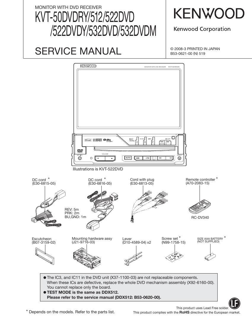
Illustrations is KVT-522DVD


DC cord * DC cord * Cord with plug Remote controller *
(E30-6815-05) (ESQ-681605) (E30-6813-05) (A70-2083-15)
/ gig

REV: 5m / ,

PRK: 2m ///

BU.GND: 1m 5 RC»DV34O
Escutcheon Mounting hardware assy Lever Screw set SIZE AAA BAI'I'ERY *
(807-3159-02) (J21-9716-03) (D10-4589-04) x2 (Mag-1758.15) (NOT SUPPLIED)

xi

gee

OThe IC3, and |C11 in the DVD unit (X37-1100-03) are not replaceable components.
When these |Cs are defective, replace the whole DVD mechanism assembly (X92-6160~00).

You cannot replace only the board.
This product uses Lead Free widen.

OTEST MODE is the same as DDX512.
* Depends on the models. Refer to the parts list. This product complies with the ROHS directive for the European market.

Please refer to the service manual (DDX512: 353-0620-00).

Page 2

KVT-50DVDRY/512/522DVD
/522DVDY/532DVD/532DVDM

CAUTIONS IN ASSEMBLING PANEL DRIVE MECHANISM (A10-5171)

Observe the instructions described in this document when
you are going to replace the parts or components that are
shown in this document.

1. Replacement of motor flat spring

I When mounting the flat spring that shall be in contact
with the worm gear, press the spring toward the direction
shown with an arrow so that there will be no gap be-
tween the tip of the gear and the spring and then mount
the spring. The gear shall be pressure-inserted into the
motor.

I Note that there are two motors. Above operation of
mounting the flat spring is required on both of them.

Mount the flat spring
while pressing it
towards the direction
shown with an arrow
so that there will be no
clearance.

Mount the flat spring
while pressing it
towards the direction
shown with an arrow
so that there will be no
clearance.

DC Motor

Worm

Flat Spring Flat Spring

Page 12

KVT-50DVDRY/512/522DVD
/522DVDY/532DVD/532DVDM

MICROCOMPUTERS TERMINAL DESCRIPTION

12

Pin No. Pin Name l/O Application Processing Operation Description
34 PREiMUTESW O Pre-out mute (SW) H: OFF, L: ON
35 POWERiPWM 0 Frequency control of DC-DCilC
36 NAVLRX l Communication with navigation system
37 NAVLTX 0 Communication with navigation system
38 TViMciDATA/TViMciDATA 0 Data output to _TV u-com
(For other destination than K and R)
38 TV,MC,DATA/NC O (K,Fl destination)
39 VCCi
4° mmwscm I ETJFSSSLZZTSJSZ;KM
40 TV,SC,DATA/NC O (K,Fi destination)
41 V88
42 TV BP CLK/TV BP CLK 0 Communication clock with TV u-com
(For other destination than K and R)
42 TViBPicLK/NC O (K,R destination)
43 NC 0
44 TUNisDA I/O Communication data with tuner
45 TUN,SCL 0 Communication clock with tuner
46 R DATA/R DATA l DATA input from RDS decoder
(For other destination than X and (V))
45 FLDATA/NC o (x, (V) destination)
47 R QUAL/R QUAL l QUAL input from RDS decoder
(For other destination than X and (V))
47 R,QUAL/NC O (X, (V) destination)
48 EVOLiMUTEO O E-VOL front mute L: ON, H: OFF
49 EVOLiMUTE1 O E-VOL rear mute L: ON, H: OFF
50 EVOLiMUTEZ O E-VOL C-SW mute L: ON, H: OFF
51 EVOLiMUTEB O E-VOLiB-AVOUT mute H: ON, L: OFF
52 EVOLiMUTEC O E-VOLic mute L: ON, H: OFF
53 TV7JUDGE | Determination of TV,BOX if it is old or new H: Old, L: New
54 WRT7E2P I Used when writing into E2P L: Normal condition
H: When writing Into E2P
55 AVSW7PDN 0 Communication ciock with AV switch
56 VILLiR O Brightness control of R in variable illumination
57 V88
58 VILLiG O Brightness control of G in variable illumination
59 VCCZ
60 VILLiB O Brightness control of B in variable illumination
61 NTiPAL l NTSC/PAL determination signal input H: PAL, L: NTSC
62 VMUTE 0 LCD output mute control H: MUTE, L: Normal
63 X0 0 Touch panel control
64 VILLiDET 1 Variable illumination identification terminal L: F3, H: F4