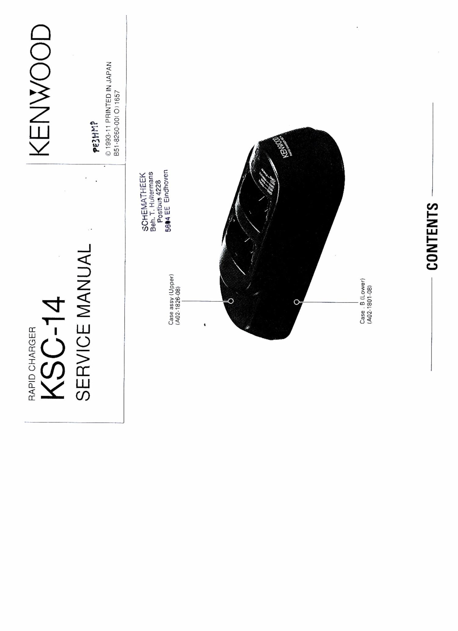
Kenwood KSC 14 Service Manual

This is the 20 pages manual for Kenwood KSC 14 Service Manual.
Read or download the pdf for free. If you want to contribute, please mail your pdfs to info@audioservicemanuals.com.

Page: 1 / 20
left right
Kenwood KSC 14 Service Manual

Extracted text from Kenwood KSC 14 Service Manual (Ocr-read)


Page 2

KSC-14

CIRCUlT DESCRIPTION

Overview

The KSC-14 is a rapid charger for Ni-Cd batteries.
PB-ll, PB-SO, PB-32, PB-33, PB-34, KNB-5/5A, KNB-6/
6A, KNB-7/7A, and KNB-9A.

Theory of Operation

The circuit for channel 1 is explained below. (See
the general flowchart in Fig. 3.) The descriptions en-
closed in brackets l i apply to channel 2.

- Battery pack detection circuit

This circuit detects a battery pack inserted in the
recharger.

For the P84 1, PB-34, and KNB-7/7A battery packs,
if the voltage at lCl PAO [PA2] is lower than the pre-
scribed value, this circuit recognizes that a battery pack
is inserted in the recharger. For other battery packs, if
the voltage at PAi [PAS] is lower than the prescribed
value, the circuit determines that a battery pack is in-
serted in the recharger.

Prescribed value: If the voltage at recharging pin 3 is
20V or higher, a battery pack is installed. and if it is
lower than 20V. one is not installed. (Fig. 1)

. Battery identification circuit

This circuit identifies the type of battery pack in-
serted in the recharger.

it determines the type of battery pack according to
the voltage at lCl PAO and PM [PA2 and PAS] and the
state of P80 [P81]. (See Fig. i for details.)

- Trickle recharging
When a battery pack is inserted, trickle current
flows to the battery pack through 01 [O7].

. Rapid recharging start

When SW1 [SW2] is turned on, lC1 PF2 [PF3] goes
high. lf 3 battery pack is inserted in the recharger, it
starts rapid recharging or goes into standby.

If the battery pack is a PB-1 1, PB-34, or KNB-7/7A,
lCi PCO [PC2] goes high, otherwise PC1 [PC3] goes
high, and transistors 01 and 02 [O7 and 08] turn on.

- Rapid recharging stop

When SW1 [SW2] is pressed again, trickle charging
returns.

if the battery pack is a PB-il, PB-34, or KNB-7/7A,
IC1 PCO [PC2] goes low, otherwise PC1 [PCB] goes
low, and transistors 01 and O2 [O7 and 08] turn off.

' Timer circuit

When rapid recharging starts, the count begins, and
when about 120 minutes elapse, IC1 PCl [PCB] goes
low and recharging is forced to be terminated.

. Short detection circuit
For the PB-i 1, PB-34, and KNB-7/7A battery packs,
if the voltage at lCl PAO [PA2] is lower than the pre-
scribed value, this circuit recognizes that the battery
pack is shorted. For other battery packs, if the voltage
at PAi [PAB] is lower than the prescribed value, the
circuit determines that the battery pack is shorted. lf
this condition continues for more than 20 minutes after
recharging begins, an error is displayed (the orange
LED flashes).
Prescribed value:

.

PB-3O ...................................................... 4.5V
PB-32, PB-33 .......................................... 5.4V
KNB~5/5A, KN B-6/6A, KNB-QA ................ 6.6V
PB-34 ...................................................... 8.7V
PB-ll, KNB-7/7A .................................... 10.8V

- Display circuit

When |C1 PDO [PD2] goes low, the LED lights in
red, and when P01 [P03] goes low, it lights in green,
according to the display contents.

The LED lights in orange by lighting both the red and
green LEDs.

For details of the display contents, see Basic Opera-
tion (page 6).

~ Reset circuit

if the PB-ll, PB-34, or KNB-7/7A battery pack is
removed from the recharger and the voltage at IC1
PAO lPA2] becomes higher than the prescribed value,
this circuit determines that no battery pack is inserted
and resets the microcomputer. If another type of bat-
tery pack is removed from the recharger and the volt-
age at 1C1 PAi [PA3] becomes higher than the pre-
scribed value, this circuit determines that no battery
pack is inserted and resets the microcomputer.

. Recharging detection circuit

This circuit checks the voltage at lCi PAO [PA2] for
the PB-1 l, PB-34, and KNB-7/7A battery packs, or PM
[FAB] for other battery packs, and stops recharging if
the battery recharging voltage reaches the peak.

. Recharging current switching

it the recharging current is BOOmA, lCl PED goes
high, and if it is 1200mA, PEO goes low according to
the battery type to switch the recharging current.

- Recharging channel selection
See the flowchart in Fig. 2.