Kenwood KRV 7050 Service Manual

This is the 113 pages manual for Kenwood KRV 7050 Service Manual.
Read or download the pdf for free. If you want to contribute, please mail your pdfs to info@audioservicemanuals.com.

Page: 1 / 113
left right
Kenwood KRV 7050 Service Manual

Extracted text from Kenwood KRV 7050 Service Manual (Ocr-read)


Page 2

(R-V6050/7050

CONTENTS

FUNCTION ............................................................ 3
ACCESSORIES .......................... _, 3
DISASSEMBLY FOR REPAIR 4
REMOTE CONTROL OPERATION m6

CONTROL INDICATOR ......................
BLOCK DIAGRAM .............
CIRCUIT DESCRIPTION
ADJUSTMENT .....
REGLAGE .........

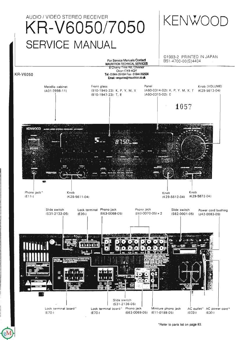
KR-V7050

Front gIass
(810494523): K, P, Y, M, X
(8104947-23): T, E

Metallic cabinez
(ACT-299841)


ABGLEICH .............................................................. 45
ADJUSTMENT/REGLAGE/ABGLEICH ..... 45
WIRING DIAGRAM .................................. ...47
PC BOAD ..................................................... 51
SCHEMATIC DIAGRAM (KR-V6050) ..... M57
SCHEMATIC DIAGRAM (KR-V7050) .......... 55
EXPLODED VIEW (UNIT) ............................ 81
PARTS LIST ................ 83
SPECIFICATIONS 107

PaneI Knob
(AGO-031202) (K296613704)

Phone jack Knob

51 1" (29-561 1-04)
Slide switch
(331-213205) (5204 >

Lock Termina! board

Refer to parts Iisx on page 83,

Lock termina! board" Phono IGCk
(553-0068-05I

Lock Terminal board
IE70-) [£704

Knob Knob

(K296612434) (ZS-567204)
Power cord bushing
IJ42«0083-05)

Phone jack
[263-0070-05)
I

Phone jack Miniture phone jack AC outlet AC power cord ~
lE63-0069AOS) IE1 1-0188-05) IE30»I (EGO-I

Page 4

KR-V6050/705O

(D

11

DISASSEMBLY FOB REPAIR

Remove the 6 screws 0, press the 2 claws 9 of
the sub-panel, and remove the front panel.
Remove the 6 knobs 9 and the nut e.

Fiemove the 4 screws 6 and remove the sub~panel
together with the circuit board.

Remove the 6 screws 6, pull the 14 claws 0 of the
sub-panel] and remove the circuit board.

Remove the 6 screws 6, and pull out the
chassis
Remove the screw 9, and disconnect the phone jack
by pressing the claw (D.
The volume comrol (X13) (DIS), the loudness and
the balance (X13) (IE/31 can be removed when the
2 screws 0 and the nut ® are removed. l-oil

659

, Remove the 4 screws @.
. Remove the 7 screws we
Hold the extremity of the 2 clamps with tweezers and
the like, and remove the circuit board 9.
. In the case of the E. Ttype, remove the parallel lead
wires of CN4.
'When assembling, take care for the cord not be
caught between the two circuit boards. 6.

Page 34

KR-V6050/7050
crncurr DESCRIPTION

Digital delay IC: YM7128B (X14: IC304, 402)
Si-Gate CMOS PROCESS LSl

®x1
@XO Timing

Generation
02¢ @voo
.VSS
@AIN AID VM Digital Delay ©AVDD
Conversion T T7 T T T4 T3 T2 T1 GU 9 AVSS
@CH GL2
@CV sales? GL3
generation GL4 D/A
GL5 2fs Conversron ®LO
GL6
GL7
GL8
Gfil
SCI .

®AO Microprocessor 6R2

@DIN interface (3"3
GR4 D/A
GR5 Conversion .RO
GRG

©ITI 6R8

Pin Function description

Pin connection Tehnolinal Terminal name 0 Function
1 VDD _ Digital system +5 V
V power supply
VDD CG .3 C 2 AVDD __ Analog system +5 V
power supply
AVDD Q) @j DIN .
3 CH 0 Sample holding capamtor
CH add-on terminal
E® ®j A0 Analog signal input term-
4 AlN I nal lEntered by CV vol-
AIN D69 @j SCI rage reference).
5 CV O AID conversion reference
CV E© @] XI voltage output
Test input terminal (Nor-
T |
[TI E© ® xo 6 / I + mally unconnected)
7 LO 0 L-channel outpul (Analog
LO E® VSS outpurl
8 HO O R-channel outpur (Analog
90 C @ :| AVSS WW"
9 AVSS - Analog system ground
l0 VSS - Digital system ground
Crystal oscrllalor {standard
1 1 X0 0 716 MHz) connection
(Xl is the analog input ter~
12 XI l minal when using external
clock)
13 SCI I Data shift clock input
terminal
14 A0 ' Address/data identification
signal input terminal
is DIN | Dale Input terminal 37
16 lIC . I+ lnltlal clear terminal

Terminals bearing the mark " + conraln built-in Dull-uu resistorr