Kenwood KRV 7030 Service Manual

This is the 35 pages manual for Kenwood KRV 7030 Service Manual.
Read or download the pdf for free. If you want to contribute, please mail your pdfs to info@audioservicemanuals.com.

Page: 1 / 35
left right
Kenwood KRV 7030 Service Manual

Extracted text from Kenwood KRV 7030 Service Manual (Ocr-read)


Page 1

65RI/ 32 6 30

AUDIO VIDEO STEREO RECEIVER KENWOOD
KR-V703O

SERVICE MANUAL

((3) 1991-3 PRINTED IN JAPAN
851-4313AOO(S) 3118

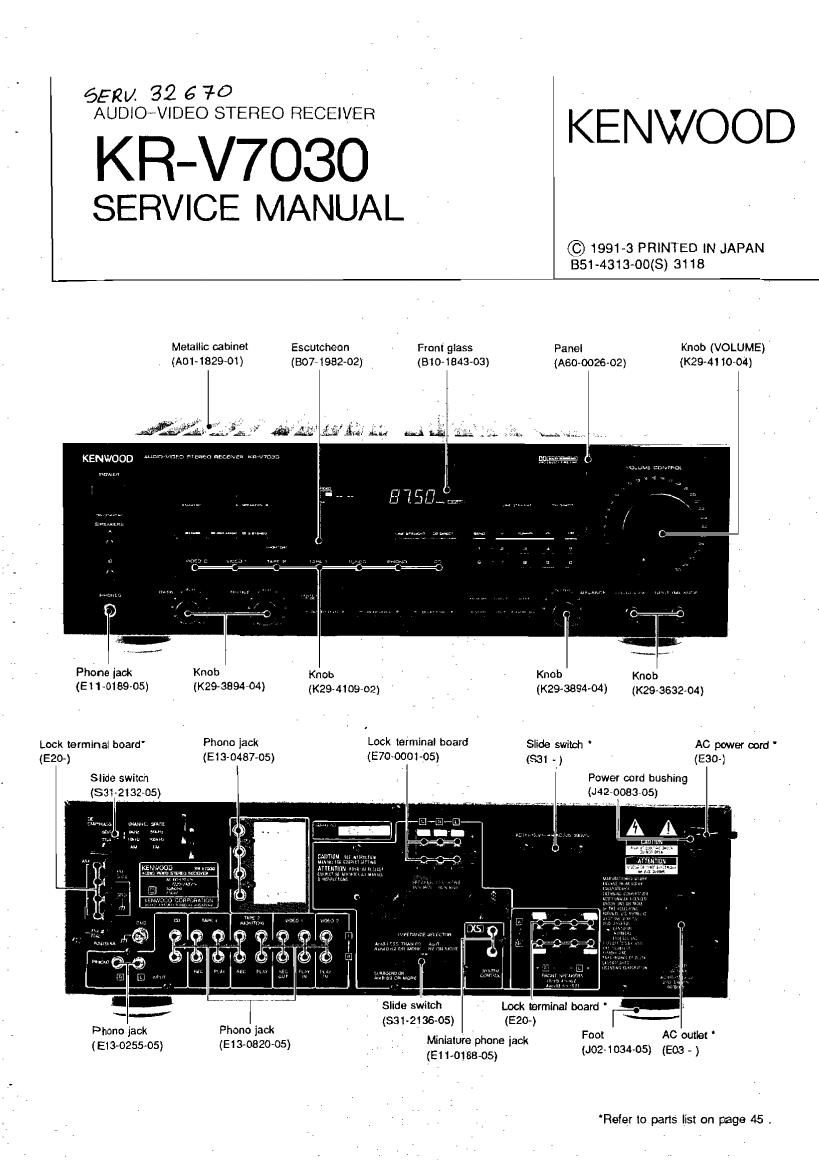
Melanie cabinet Escutcheon ant giass Panel Knob (VOLUME)
, 0501482901) (8077198202) (Bio-1843433) (AGO-002602) (K294! 10-04)

PhOne jaw Knob Knob , , Knob Knob

(E I 1 mas-cs) (K294894704) (29.410903 (K293594534) (K293632704,
Lock terminal board" Phone 135k L°°k 16 mind beard Siide switch ' AC power can! '
(ego) (macaw-05) (900001-135) ($31 .) ' (EGO-l
Slide switch Power cord bushing
(531213205) (J42*0083-05)

- r V W [ a Slide SWIG?! ' Lock nerminal board '
Pb _ w Ph ck (331-213645) (E20) -'
om 3 mo 13 - - . . Foo! AC outlet
> _ MmatuI'e ne jack
(Em-025505) (E13 0820 05) _ pho _ _ _
(EH-018805) 02 34 05) (503 )

Rsfer to parts 5: on page 45 .

Page 2

KR-V7030

CONTENTS

ACCESSORIES ....... 2 WIRING DIAGRAM 16
DISASSEMBLY FOR . 3 PC BOARD... 19
REMOTE CONTROL OPERATIO .4 SCHEMATIC DIAGRAM 27
BLOCK DIAGRAM .5 EXPLODED VIEW 43
CIRCUIT DESCRIPTION .6 PARTS LIST.... 45
ADJUSTMENT .. 6 SPECIFICATIONS 51

Accessories

FM indoor antenna ,. AM loop nntenna

(TDD-0|75-I75) ago-0174415)

Antenna mprnr ' Leap anmm holder .

175 Mon m tars-29154»)

(Except for some lteas) "

(T90v0177-05) GB

Bananas Remote control unit

(as nrAA) .. .......2 70.050503

AC plug Idiptnr . 1

(EWOHHS) FOR GENERAL MARKET
(5034304505): FOR UK

For the unit with . European
Ac plug in IVCIS mhsr than
Europe,

KR-V7030

DISASSEMBLY FOR REPAIR

Note: Remove the case before starting.

Removing the from panel and sub-panel.

r. Remove the three screws 0 at the top. the four
screws @at the bottom. and the two claws 9, then
remove the trout panel.

2. Remove the MAIN VR and each knob e , rev
move the two screws . then remove the sub»
panel,

Removing the main PC board

1. Remove the two screws 0.

2. Remove the etght screws 9.

3. Remove the one screwo.

4. Remove the five screws 0

5, Remove the two claws 0 . then remove the main
PC board in the direction of arrow 0

How to remove the repairing chassis

1. Remove the one screw. and tom 0 .
2, Cut the srx parts Out the repairing chassrs,
3. Remove the claw of holder 9.

After repair

4. Turn the repairing chassrs 180 degrees In the arrow
dtrection o .

5. Insert the two claws 9 into main chassrs.

6. Lock to the holdero. .

7. Luck to the rriam chassis by eight screws (M316)

5. Look to the root by screw (1).