Kenwood KRFV 7771 DE Service Manual

This is the 50 pages manual for Kenwood KRFV 7771 DE Service Manual.
Read or download the pdf for free. If you want to contribute, please mail your pdfs to info@audioservicemanuals.com.

Page: 1 / 50
left right
Kenwood KRFV 7771 DE Service Manual

Extracted text from Kenwood KRFV 7771 DE Service Manual (Ocr-read)


Page 1

KRF7V7771D(E COVER1,1( 99.10.28 7:57PM \°-/2

AUDIO VIDEO SURROUND RECEIVER

KRF-V7771 D/V7771 DE

SERVICE MANUAL
(E,T type)

KENWOOD

©1999-1/851-5498-00 (K/K) 1612

This manual is available for repair in the Europe and England markets.
Please refer to the original manual (B51-5426-00) if need the information in the USA and Canada and other

markets.
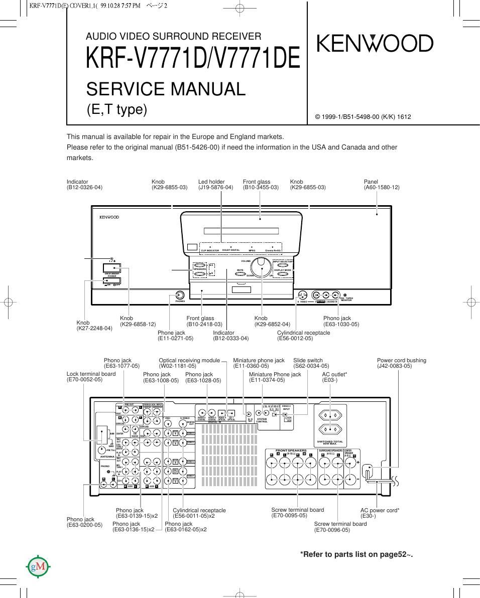
Indicator Knob Led holder Front glass Knob Panel
(B12-0326-04) (K29-6855-03) (J19-5876-04) (B10-3455-03) (K29-6855-O3) (AGO-158042)
f \
KENWOOD
l:|
.La
f© O ( C CIR, ,
/\ ma Is-xw mm
k / \
Knob Knob Front glass Knob Phono jack
K29-6858-12 B10-2418-03 K29-6852- 4 E 3-1 3 -05
(K27-2248-04) I I _ I _I I °_I _ I 6 0 0 I
Phone Jack Indicator Cylindrical receptacle
(E11-0271-05) (312-0333-04) (E56-0012-05)

Phono lack

(E63-1077-05)
Lock terminal board
(E70-0052-05)

Optical receiving module _
(W02-1181-05)

Phono jack

Phono jack
(E63-1008-05)

(E63-1028-05)

Miniature phone jack
(E11-0360-05)

Miniature Phone jack
(E11-0374-05)

Slide switch
(862-0034-05)

AC outlet
(503-)

Power cord bushing
(J42-0083-05)

I
5??? $53: l
Gs E I i121
aria w


swichEo YDYAL
mw uux

snouvspuxans

suRRwanPEAKEIs
fl HIM-15mm E

El A

max
5mm
1w

D

()0

/\

Of

\

/

\
/|

\

O

\/\

I

Phono lack Cylindrical receptacle
Phono lack (E63-0139-15)X2 (E56-OO11-05)X2
(E63.0200.05) Phono jack Phono lack

(E83-0136-15)X27 (E63-0162-05)X2

Screw terminal board

AC power cord
(570-0095-05)

0230-)
Screw terminal board
(E70-0096-05)

*Refer to parts list on page52~.

Page 2

KRFEV7771D(E) COVER1,1( 99.10.28 7:57 PM Nb? 3

KRF-V7771 D/V7771 DE

CONTENTS / ACCESSORIES / CAUTIONS

Contents

CONTENTS / ACCESSORIES / CAUTIONS
CONTROLS .....................................
DISASSEMBLY FOR REPAIR
BLOCK DIAGRAM ............
CIRCUIT DESCRIPTION ..
ADJUSTMENT .......................................................... 13

Accessories

Remote control unIt (1)
(A7071269705)


(Rchosm)
Battery cover(AO971115708)

" AM leap amenna (1) (Tgorosaam) 777777777777 .

Loop antenna stand (1)
(J1973645705)

WIRING DIAGRAM ......
PC BOARD ...............
SCHEMATIC DIAGRAM.
EXPLODED VIEW
PARTS LIST ................. ..
SPECIFICATIONS ..................................................... 67

BatterIes(R6/AA) (4) FM indoor antenna (1)

(T9070836705)

rx
\/

Cautions

I-tMHD I'Set'tl'e n'icrocurpla

The microcomputer may malfunction (impossibility of operation,
erroneous display, etc.) when the power cord is unplugged and
plugged in again while the unit is in ON mode or due to other
external causs. lnthis case, executethe pmcedureon the rightto
raet the microcomputer and return the unitto the normal condi~
tion.

0 Resetting the microcomputer clears the memory you entered and

returns it to the initial condition when the unit left the factory.

0 With the power cord plugged in, turn the POWER keyto
OFF.

BWhile holding down the |/(') (0N/ STANDBY) key, prss
the POWER key.

r Memory backup function

Please note that the following items will be deleted from
this units memory if the power cord is disconnected
from the AC outlet for approximately three days.

0 The input selection is cleared and the Tuner" input is selected.

0 The volume settIng Is cleared and the volume is set to -66 dB".

0 The receiving band setting Is cleared and the FM" band is
selected.

o The trequency setting is cleared and 87.5 MHz is selected.
0 The preset station memory is cleared.
o The surround setting is cleared and reset to the InItIal condition.

Page 19

F\
\/

KRFRV7771D(E) PCBSD2.2P( 99.10.28 8:53 PM \°~/ 1 E;

O
I:
w
E u
TUNER UNIT 2. g
(X1173822770) ((2/7) cmz
,-Iz II-I
1 I c925 0627 ( CNS
I Si Eé FM §§ 3% NR 73 mp 25 fig 2% I )-® VoLUME TONEVDATA
I csmzv L)? >r II KISSED no 0: *EE SE. I CSZAI R625 6626 32 8338 2)-© VoLUME TONEVCLK
R990 Leos m 22°F I 0022 3 )-® ToNEsTB
mm m + N
| H o. .1 mm
'W In In 3% EN 5 @ VOLUMEVSTE
oeoi r m an I
I $ K § é <3 I (53; gx Ram 24 5 DGND
o v K ' Na: E Z 0637 R633 DE $2 68 $3 ggvflvlgEE/siv © EEMUTE w
I gé $ é g é iDuifl K n ml (2303 cam 45 I7V
o, + I: m LI m E 88 38 oms 0068
R642 >§ >§ >§ >§ >§ s s >§ « 43V 0638 mm 0% $938? W
I R641 100K IDK E: :3; 3: 3: 3: 3% g: 35% §§ ( SW 10qu fig ES 465V @ TONE oUT Lch
W a a a a 5 5 V I a 2 K" 0" 5322; @ GND
I qE7V<- ® TONE IN Lch .
|C44 CAUTION' For continued safet
s E m m N, N N E 2 END . _ _ y,
2 DECODEFI a 2 m0 E re lace safet critical corn onents onl
O W U ANTIVEIFIDIE 3X 2 C) (/2 TONE IN Fich . I
I EE 5 LADDER RESISTOR 0 ILADDER RESISTOR > ® END With manufacturer 5 recommended
>J-o-I'Im-o '\ ANALDGSW ANALDGSW parts (refer to parts list). A indicates
:IPDET II/ @ TONE oUT Rch _ _ _
I L602 STSEIEED z> safety critical components. For contin-
I . 11D: 5 l IEIEI- 3 17 ued protection against risk of fire,
a V IF I\ I3bii LATCH mom I replace only with same type and rating
I l l/ E _ Ex luse s . To reduce the risk of electric
s 5, I 5, '- Eg h k i k t ' t
(EITIXITYPE E 2 I SD _ D- _'ISOVA(E I A501 (W02E2584'05l -FM FRONT END 35} g . COMP W Z L L % CDDEDETECIT II 0237; an W at ax measurements shall be carried out
I DISTORTIONISTI -IL: 0 SVMETER' 4 CIRCUIT EDbiSHFTREG'STEHC'RCU 75an 33 E $9 3% $3 (exposed parts are acceptably insulat-
VT 5 Rm 80 ed from the supply circuit) before the
E24
I I 220 AM/FM I ANALOG sw ANALOG sw Ea appliance is returned to the customer.
J60I cI 02 c4 E - / IF OUT 7 IF'BUFF ' R326
3 I 27p lap 05? . 5P m V TUNING STEREO g LADDER RESISTOR 2 LADDERREsIsToR D 52K
FM 75 C I II I 5 1: | DRIVE DRIVE I S 8 E
2 ANTI L2 X x E g g 1 N7
7 ,_,WN_ m m N m N N s m m
2 GND 4 .2, m m L 9 I 43V E E E E E 3 >9er
Pot-L004 E é" E 5 m E E mu" m on» E D (W) Z can: T MIN 7(2st
l DI l 3 S u a: - 5% E ; I (3ND Vcc ~- 7 am 1 17V GND
I E m E o E s -
GND SIGND L) N o a I g I -933? Imav I W W (D ErLch IN
'- AM I 5 7 5 R" E ' ' ' 3 ' c304 (2302
4 D 100 0400 Vcc 6 a a a (a .
~ - m D a : >§ ss .3 as >3 >3. as ssv >§ 35v 2% 5 68 © 5 0 9
4 GND ' ' E n E R5 v v mud 13 w as (VI 2°? 0507 0% ® GND
W LI 023 age a E E v E T -v we Ra 7x 533% 9
I FETI 28K302 E 5 WE TR? 00P X 38 5a 00 E2 Ea >> (3 BIG" OUT
I TRI lzsczm @ IRS 7 _' r K SW 5 5 ® GND
Eso ' a a l 3 ' t
I - I TR2,3 '25c2413 8P :3 E 050 I E W - gene 93 8,3220 gé I E MUTE
I D174 :svczzn or 55 s 5 BUFFER I I I cm (50v) U
4 I I KVIMU E c; ' e was an as 99 t T' I 35 X ' 3% m1 =3 3-" I I
o N LI 921;; gt; 8" SE n; 0.5 as o :I' an ES x
o o v - . it D; t 0617 m E S
I I-| 53 man gé ; é smwsyavi -SIGNALLINE
RssafisK 03 t . 07 § 5 pom/HON - (3ND LINE
I (2467?: E E 163V I #Em- +B LINE
I -- -<-E<- -BLINE
CNII
I s 3; a, m E J- DET - i043 NJMASSSD
$§ go 5 N 3 3 8 g x K R640 I044 TCQISAAP
I As: Rm gs as a g * :4; n E 2 IK R691 33K 53 I060! LA1837
E L" m w 0 31 SD Iceoz LC72I31
Io R651 R (-1 . L: >- R692 3 3K
. . fig 5 a as g 7 fl m
I 56K mg t LI' m =§ g m gs -605 m g e -L§§- oemsoeam ZSCADBRRSIDI
I 8 3,3 gg mu, I 8; m 3% 5 $1 Bx g g: to 63V 69V 00 R6 c. IK Ii Fich ZSCMISWGRI or
E. US 09 g; m , 8., 5; go E? g a 22 ascwms L6)
n m E 7 FM oET MPX I I N N ,
I V gé >§ % 5 K 17v Q602 R694 3%, 75 | ca 33% e 0602,6I26I4 ZSAI575A(R SJor
5 m. x 89 E 0°35; J-SV t5 0 5 I Is, K 0 g xosrcn zsmsseimm
I s s 3 as us 05m 5833 I W 'E ZSAWMSMGI
I (25V) as $3; (I $5) I 5 1w 1 1M GND I: oeiosn ZSDI757K
N r <: - r\ «7 D m
I r r _ g E E 8 DE 3 80 g CF602 a MPX FILTER a 1 gig at E D5 2 DAZOAU or
chm g a s m N mm In; 7 R a 7,; 8% ; 158302
I E ' 3 z N3 ' In K 5 a K >(Q Dem DAZOAK
g m m g m m .
.-. . m DI o g; __LG_07__ _ RIGK21 D503 . Roa.2EsII32I or _ _
I PSQiEREEETPEV; 0. ° on E 2 ' . Ior - - -
I SWALLOWCOUNTER iZhIIsPROGRAMABLE é ° . ER ' I W M, 4M {07/ Emma HZSSIN uNLOCK P0WER memmis DIVIDEH 0) W FM 11 av 52ng ,Isv e Elev . type voltmeter as the AM/FM signal
I DETECTOR ON g WW I__ Dell R674 D505 HD2,7ES(BZI0I _ _ _ _
RESET IE a ___J in 47K Im? 45V 7 IBV H252 7N(BZ) generator Is speCIiied to the condi-
I -II I ' a e m 0509 aggéBEISIISSIM tions as shown in the list below. The
a a >
I | c2BIE Ic::>| DATASHIFT HEGISTERLATCH IczaIDNIVERSALwUNvER g a w E: 4)-@ mom DEII,6I3 , MAIII measurement value may vary
[W] E N m l 5)-@ mom DEIZ : ISSISS OI depending on the measuring Instru-
I m X m 37V§ I; 3)-® MOE HssmA ments used or on the product. The
E N 24V $8 135V] 0 DEIS :UIBC44 - - -
I E m m S ; MI/(my K 7 [35V] mm QGIZ me e)-@ moo value shown In ( ) IS actual reading
I 3§ g§ III/WWI I -" SK Q measured In the AM mode.
Isa- «53 50V _
» T. MUTE 27V R677 T
I DRIVE 1 J K I MODE CARRIER MODULATION ANT INPUT
RMBIK 6 5V FREQUENCY DEVIATION
I Heuagx 5 $5083 WHeoI FM QSMHZ IRHz STEREO 67.5RHz 7.5kHz(F'Ilot) SOdB
I R646 3 M J I AM 1000(999)l 4
I HGASSSK I

KRF-V7771 D/V7771 DE

7 KFlFrV7771DIE.T) (1/5)
KFlFrV7771DE(E2) (1/6)

Y05-3862-70