Kenwood KRFV 6100 DS Service Manual

This is the 30 pages manual for Kenwood KRFV 6100 DS Service Manual.
Read or download the pdf for free. If you want to contribute, please mail your pdfs to info@audioservicemanuals.com.

Page: 1 / 30
left right
Kenwood KRFV 6100 DS Service Manual

Extracted text from Kenwood KRFV 6100 DS Service Manual (Ocr-read)


Page 1

KRFVVSIOOD IIVI 06.7.25 2 33 PM \°»/1 / N
K

AUDIO-VIDEO SURROUND RECEIVER

KRF-V51OODN51OOD-S KENWOOD

KRF-V6100DN6100D-S
SERVICE MANUAL ©2ooe.5pR.NTED.NKOREA

851-5985-00 (K/K) 219


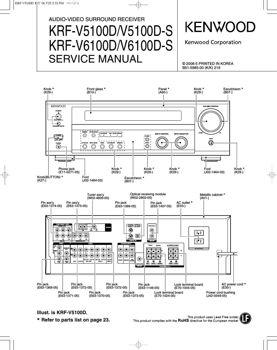
Knob * Front glass * Panel * Knob * Esoutoheon *
(K29-) (310-) (A60-) (K29-) (1307-)
KENWOOD vDLquE comm
o F l A
90 U
1 © © . My gm? mfi uluanonoL .mrsmcmn
Z 1 L__________ :©: © © 6
@- 1 © © © © 0 19:

:6

Phone jack Knob * Knob * Knob * Foot Knob *

(E11-0271-05) (K29-) (K29-) (K29-) (J02-1464-03) (K29-) fi
Knob(BUl'l'ON) * Foot Escumheon * 1»
(K27-) (J02-1464-03) (807-)

Tuner assy Optical receiving module Metallic cabinet *
(W02-4609-05) (W02-2802-05) (A01-)
Pin ass' Pin assy Pin jack Pin jack AC outlet *
(E63-1374-05) (E63-1375-05) (E63-1369-05) (E63-1407-05) (E03-)
0


ooAxlu ovrlou
vbnmz on m

-I|E

mam um

SURROUND

mm vuvw
mm l

mu w
mm

Pin jack Pin jack Pin 'ack Pin jack Lock terminal board AC power cord *
(E63-1368-05) (E63-1372-05) (E634 372-05) (E634146-05) (E704 004-05) (E30-)
Pin jack Pin jack Pin 'ack Lock terminal board Power cord bushing
(E634 371 -05) (E63-1370-05) (E634 373-05) (E704 024-05) (J42-0349-05)
Illust. is KRF-V5100D.
* . This product uses Lead Free solder.
Refer to parts St on page 23. This product complies with the ROHS directive lprthe European market.

(9 lT

Page 2

J

KRFVVSIOOD II\T 06.7.25 2 33 PM a? 2

KRF-V51OOD/V61OOD

ACCESSORIES / CAUTIONS

Accessofies

FM indoor antenna (1)
(T90-0877-05)

AM loop antenna (1)
(T90-0893-05)

Remote control unit (1)

Batteries (R03/AAA) (2)
(A70-1670-05)

Caufions

Information on Disposal of Old Electrical and
Electronic Equipment (applicable for EU countries
that have adopted separate waste collection

systems)
Products With the symbol lcrossedrout Wheeled binlcannot
be disposed as household waste.
Old electrical and electronic equipment should be recycled
atafacility capable of handling theseitems and theirWaste
_ byproducts.
Contact your local authority for details in locating a recycle facility
nearest to you.
Proper recycling and waste disposal Will help conserve resources
Whilst preventing detrimental effects on our health and the
enVironrnent.

Memory back up function

Please note that the folloWing items Will be deleted from the unit's
memory it the power cord is disconnected from the AC outlet for
approximately 1 day.

I Power mode

I Input selector settings
I Picture output

I MD/TAPE settings

I Input mode setting

I Speaker settings

I Speaker ONIOFF I Sound mode settings
I Volume level I Distance setting

I BASS, TREBLE, INPUT level I Listen mode setting
I TONE ON/OFF I Broadcast band

I LOUDNESS ONIOFF I Frequency setting

I ACTIVE E0 mode I Preset stations

I Dimmer level I Tuning mode

Rescuing the Microcomputer

The microcomputer may malfunction (unit cannot be operated,
or shows an erroneous display) it the power cord is unplugged
while the power is ON, or due to some other external factor. If
this happens. execute the following procedure to reset the
microcomputer and return the unit to its normal operating
condition.

With the power cord plugged in, turn the POWER
ONIOFF key OFF. Then, while holding down the ON]
STANDBY 0 key, press the POWER ONIOFF key.

I Please note that resetting the microcomputer Will clear the contents
of the memory and return the unit to the state it was in when it left
the factory.