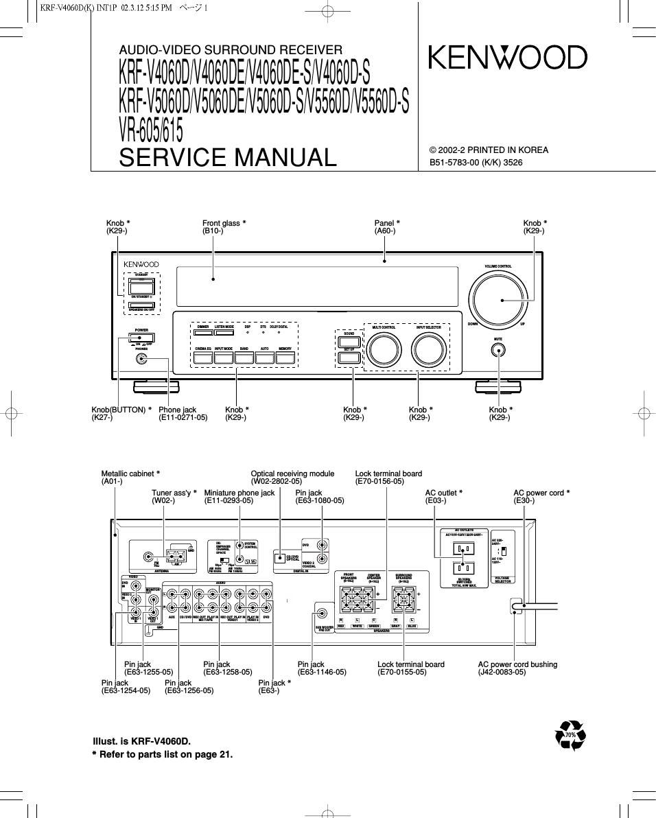
Kenwood KRFV 5560 DS Service Manual

This is the 36 pages manual for Kenwood KRFV 5560 DS Service Manual.
Read or download the pdf for free. If you want to contribute, please mail your pdfs to info@audioservicemanuals.com.

Page: 1 / 36
left right
Kenwood KRFV 5560 DS Service Manual

Extracted text from Kenwood KRFV 5560 DS Service Manual (Ocr-read)


Page 2

KRFEV4060D(K)INT1P 02.3.12 5:45 PM «Hs/7. /\

KRF-V4060D/V5060D/V5560D/VR-605/615

CONTENTS / ACCESSORIES / CAUTIONS

r\
\/

Contents

CONTENTS / ACCESSORIES / CAUTIONS....
CIRCUIT DESCRIPTION.
PC BOARD .................
SCHEMATIC DIAGRAM


Accessories

EXPLODED VIEW
PARTS LIST.
SPECIFICATIONS

,
Remote control unit (1)
Refer to the table
on this page below.

D
D
0

AM loop antenna (1)
(Tee-ossz-os)

REMOTE CONTROL vs MODEL

FM indoor antenna (1)
(T90-0877-05)

Batteries (R6/AA) (2)

AC Plug Adaptor (1)
(E03-0115-05)
g V Use to adapt the plug on the
" power cord to the shape of the
wall outlet.

use is necessary.)

(Accessory only tor regions where

REMOTE DESTI- REMOTE DESTI-

MODEL PART CONTROLit NATION MODEL PARTS CONTROL# NATION
KRF-V4060D ET KRF-VSOBOD-S A70-1563-05 RC-R0620 MX
KRF-V4060DE A70-1566-05 RORoezs E1 KRF-V5060D»S A70-1565»05 RC-R0622 E3T1
KRF-V4060DE-S E2 KRF-V5560D A70-1564-05 RC-R0621 Y
KRF-V4060D-S A70-1564-05 RC»R0621 MX KRF-V5560D A70-1566-05 RC-R0623 E
KRF-V4060D-S A70-1566-05 RC-R0623 E3T1 KRF-V5560D»S A70-1564»05 RC-R0621 MXH
KRF-V5060D A70-1563-05 RCRoszo Y KRF-V5560D-S A70-1566-05 RC-R0623 E3T1
KRF-VSOGOD ET VR-605 A70-1564-05 RC-R0621 KP
KRF-VSOGODE A70'1565'05 RCROBZZ E1 VR-615 A70-1563-05 RC-R0620 KP
Cautions

Resetting the Microcomputer

The microcomputer may malfunction (unil cannot be operated. or
shows an erroneous display) it lhe power cord is unplugged while the
power is ON, or due to some other external taclor. If this happens,
execute the following procedure lo resel lhe microcomputer and
return the unit to its normal operating condition.

Unplug the power cord from the wall outlet, then

- Power mode. - Distance setting.
- Please nole that resetting lhe microcomputer will clear the conlents ' "let SSIGCIOF SERIHQS- ' Input mode sean-
ol the memory and return lhe unit to Ihe state It was in when it lett - Picture output. - Midnight mode setting-
the lactory - Speaker ON/OFF. - PRO LOGIC || mode setting.
- Volume level. - Broadcast band.
F° "9 U-S-A- and canada - BAss, TREELE, INPUT level. - Frequency setting.
- Dimmer level. - Preset slations.

For other countries

plug it back in while holding down the POWER key. I Eggfidfgefi'g :Elngaféfim/OFF
- Speaker settings. - LOUDNESS ON/OFF.

With the power cord plugged in, turn the POWER key
OFF. Then, while holding down the ONISTANDBV No
key, press POWER.

Memory back up function

Please note thal lhe lollowing items will be deleled trorn lhe unit's
memory it the power cord is disconnected lrom the AC outlet lor
approximately 3 days.

- SW RE-MIX ONIOFF.

Page 5

r\
\J

CIR 02.3.125:13PM Ks/5

/\
\/

KRF-V4060D/V5060D/V5560D/VR-605/615

CIRCUIT DESCRIPTION

Pin No. Pin Name IIO Description
24 CODEC OVER I Overflow detection port for CODEC analog signal.
25 RESET l Reset signal input for microcomputer.

26 CODEC CSN 0 Chip select for CODEC.
27 RDS DATA 0 RDS signal data output.
28 S BUSY I/O Serial busy signal input/output.
29 8 DATA l/O Serial data signal input/output.
30 MODEL TYPEO I Discrimination port for model type.
31 REMOCON I Signal input for remote controller.
32 CODEC INT I Detection port for digital signal error.
33 RDS CLK | Clock input for RDS demodulator IC.
34 DSP INTREQ I Detection port for DSP INTREQ.
35 MODEL TYPE1 I Discrimination port for model type.
36 FL DIN 0 Data output to FL driver.
37 FL DOUT I Data input from FL driver.
38 FL CLK O Clock output to FL driver.
39 FL STE 0 Strobe output to FL driver.
40 PLL DATA 0 Data output to PLL IC.
41 PLL CLK O Clock output to PLL IC.
42.43 NC - Unused.
44 PLL CE 0 Chip enable output to PLL IC.
45 PLL DO I Data input from PLL IC.
46 T MUTE O Mute signal output to PLL IC.
47 STEREO I Stereo signal input from PLL IC.
48 PLL SD I SD signal input from PLL IO.
49 MULTI ENCA I Encoder (X14, $813) signal input.
50 MULTI ENCB I Encoder (X14, $813) signal input.
51 SEL ENCA I Encoder (X14,8814) signal input.
52 SEL ENCB I Encoder (X14,SB14) signal input.
53 VOL. ENCA I Encoder (X14,8815) signal input.
54 VOL.ENCB I Encoder (X14,SB15) signal input.
55 CH SPACE I Discrimination port for channel space.
56 SP RLY 0 Control port for speaker relay.
57 C/SW RELAY 0 Relay control for center and sub woofer speakers.
58 SURRRLY 0 Relay control for surround speaker.
59 PWR RLY 0 Control port for power relay.
60 PACK CONT. 0 Power pack control.
61 V. MUTE O Mute control for video output.
62 LIMITER 0 Power control for A class.
63 A. MUTE O Mute control for audio output.
64 SEL DATA 0 Data output to analog switch IC(X08,IC705).
65 SEL. CLK O Clock output to analog switch IC(X08,IC705).
66 SEL. STE 0 Strobe output to analog switch IC(X08,IC705).
67 VIDEO CTFILA 0 Video switch control.
68 VIDEO CTFILB O Video switch control.
69 -6 ATT O -6dB attenuater control.
70 VOL. DATA 0 Data output to system IC (X09,|0202).
71 VOL. CLK O Clock output to system IC (X09,|0202).
72 VOL. LATCH O Latch output to system IC (X09,IC202).
73 STANDBY LED 0 Control port for STANDBY LED(X14,D808).
74 DTS LED O Control port for DTS LED(X14,D807).
75 DOL DIG LED O Control port for DOLBY DIG LED(X14,D806).
76 DSP LED 0 Control port for DSP LED(X14,D805).
77 CE2 l Detection port of chip enable 2 for microcomputer.
78 CE1 | Detection port of chip enable 1 for microcomputer.
79 DEGITAL DET I Detection port for digital signal.
80 OHS OVFI CHK | Selection of cut-off frequency for HPF/LPF. L : 80Hz H : 120Hz