Kenwood KRFV 5200 D Service Manual

This is the 40 pages manual for Kenwood KRFV 5200 D Service Manual.
Read or download the pdf for free. If you want to contribute, please mail your pdfs to info@audioservicemanuals.com.

Page: 1 / 40
left right
Kenwood KRFV 5200 D Service Manual

Extracted text from Kenwood KRFV 5200 D Service Manual (Ocr-read)


Page 1

KRFV5200 D KENwoov

KR F-V5200 D-S

SERVICE MANUAL

Kenwood Corporation

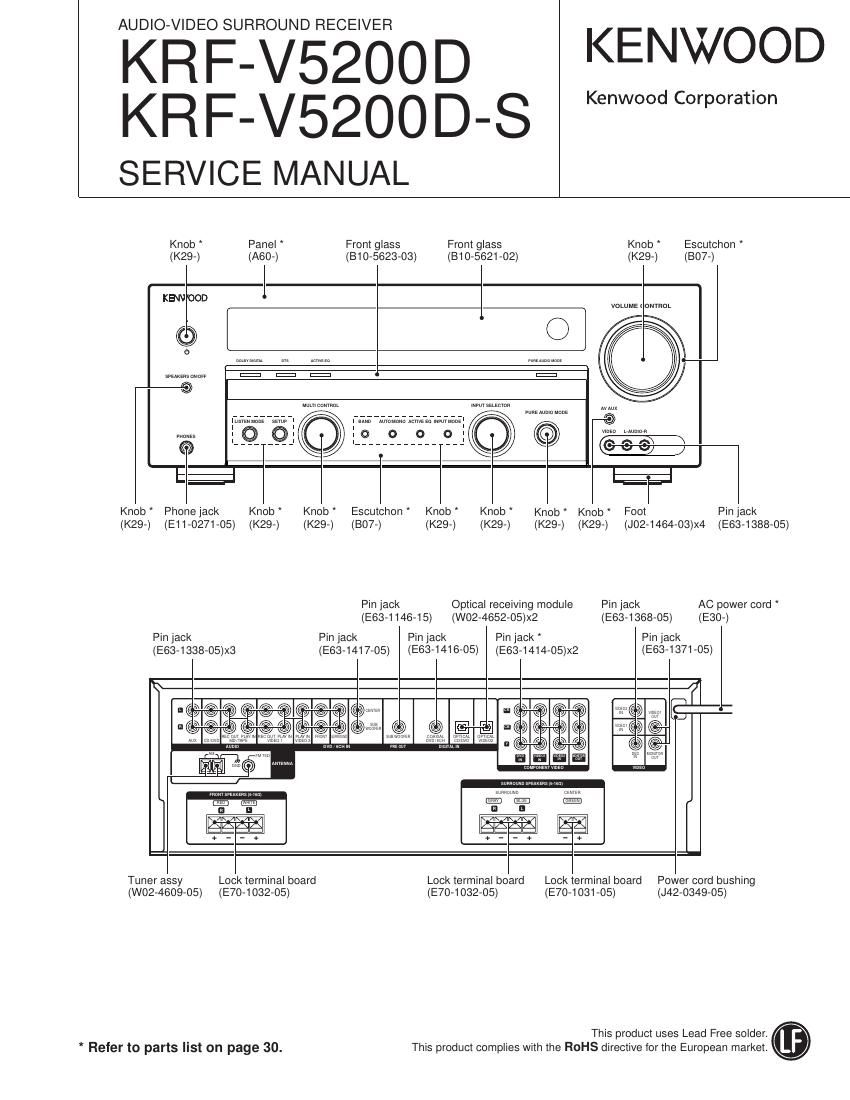
Knob Escutchon

Knob * Panel Front glass Front glass
(K29-) (A60-) (810-5623-03) (B10-5621-02) (K29-) (807-)
KEWOOD l
mum t ONYROL
t \
w ......... m a .......... .7
0
more»; 131:? WWW A5
DEO LAUNCH
1 O Q 1 CO) @ :fi a
((3 7 7 7 7 7 7 7 7 C V U

t; E;

Knob Phone jack Knob Knob * Escutchon " Knob Knob Knob Knob Foot Pin lack
(K29-) (E11-0271-05) (K29-) (K29-) (807-) (K29-) (K29-) (K29-) (K29-) (J02-1464-O3)x4 (E63-1388-05)
Pin jack Optical receiving module Pin jack AC power cord
(E63-1146-15) (W02-4652-05)x2 (E63-1368-05) (E30-)
Pin jack Pin jack Pin jack Pin jack Pin jack
(E63-1416-05) (E63-1414-05)x2 (E63-1371-05)

(E63-1338-05)x3 (E63-1417-05)

Lock terminal board Power cord bushing

Tuner assy Lock terminal board Lock terminal board
(E70-1032-05) (E70-1031-05) (J42-0349-05)

(W02-4609-05) (E70-1032-05)

This product uses Lead Free solder.
This product complies with the ROHS directive for the European market.

* Refer to parts list on page 30.

Page 2

KRF-V5200D

ACCESSORIES [CAUTIONS

Accessofies

FM indoor antenna (1)
(T90-0877-05)

AM loop antenna (1)
(T90-0893-05)

Remote control unit (1) Batteries (R03) (2)

RC-R0517 (-)
(A70-1719-05)
0000 mm an
egg {Eat l V

Caufions

Information on Disposal of Old Electrical
and Electronic Equipment (applicable for EU
countries that have adopted separate waste
collection systems)

P roducis with the symbol (crossed-out wheeled
bin) cannot be disposed as household waste.
Old electrical and electronic equipment should
be recycled at a facility capable of handling
these items and their waste by products.
Contact your local authority for details in locating a
recycle facility nearest to you.
Proper recycling and waste disposal will help conserve
resources whilst preventing detrimental effects on our
health and the environment.

Resetting the Microcomputer

The microcomputer may malfunction (unit cannot be

operated, or shows an erroneous display) if the power

cord is unplugged while the power is ON, or due to

some other external factor. If this happens, execute

the following procedure to reset the microcomputer and

return the unit to its normal operating condition.

While holding down [(1)] key on the unit, unplug the

power cord and plug it back in.

- Please note that resetting the microcomputer will clear
the contents of me memory and return the unit to the
state it was in when it left the factory.

Manufactured under license from Dolby Laboratories.
"Dolby", "Pro Logic and the double-D symbol are
trademarks of Dolby Laboratories.

"DTS"and "DTS Digital Surround" @dfi

|are registered trademarks of DTS, Digital Surround
nc.

Memory back up function

Please note that the following items will be deleted from
the unit's memory if the power cord is disconnected from
the AC oufietfor approximately 1 day.

' Input selector settings

' Volume level

0 BASS,TREBLE,INPUTIeveI

- TONE ONIOFF

' ACTIVE EQ mode

0 Dimmerlevel

' Speaker settings

0 Sound mode settings

0 Listen mode setting

0 Tuner setting

Page 6

KRF-V5200D

CIRCUIT DE SCRIPTION

Pin No. Pin Name IIO Description
29 CMPREQ IN PCM audio input sampling rate clock
30 CLKIN IN Master clock Input port
31 CLKSEL IN DSP clockselector
32 FILT2 - External filterfor PLL
33 FILT1 - External filterfor PLL
34 VA - Power supply for clock generator (+2.5V)
35 AGND - Ground for PLL ofclock generator
36 IRESET IN Master resetinputport
37 DD - Pulled up
38 DC - Pulled up
39 AU DATA2 OUT Digital audio output port-2
40 AU DATA1 OUT Digital audio output port-1
41 AU DATAO OUT Digital audio output port-0
42 LRCLK IN/OUT Audio outputsampllng rate clock
43 SCLK IN Audio output bit clock
44 MCLK IN/OUT Audio master clock

*book referred to makers semiconductor handbook

0 LC 72725KV (IC761: X08) Port Description

Pin No. Pin Name IIO Description
1 RDS-lD/READY OUT RDS-lD/READY output
2 RDDA OUT RDS data output
3 Vref OUT Standard voltage output (Vdda/2)
4 MPXIN IN Base band(MPX) input
5 Vdda - Analog power supply (+3V)
6 Vssa - Analog gnd.
7 FLOUT OUT Sub carrier output(Filter output)
8 CIN IN Sub carrier input(Comparator input)
9 TEST IN Testsignal input
10 MODE IN Read mode setting (0: master, 1: slave)
11 Vssd - Digital gnd.
12 Vddd - Digital power supply (+3V)
13 XIN IN Crystal oscillator input (External standard signal input)
14 XOUT OUT Crystaloscillatoroutput(4.332MHz)
15 RST IN RDS-lD/RAM reset
16 RDCL IN/OUT RDS clock output (master), RDS clock input (slave)

*book referred to maker's semiconductor handbook