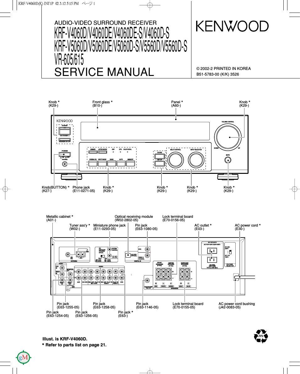
Kenwood KRFV 5060 Service Manual

This is the 36 pages manual for Kenwood KRFV 5060 Service Manual.
Read or download the pdf for free. If you want to contribute, please mail your pdfs to info@audioservicemanuals.com.

Page: 1 / 36
left right
Kenwood KRFV 5060 Service Manual

Extracted text from Kenwood KRFV 5060 Service Manual (Ocr-read)


Page 2

KRFEV4060D(K)INT1P 02.3.12 5:45 PM «Hs/7. /\

KRF-V4060D/V5060D/V5560D/VR-605/615

CONTENTS / ACCESSORIES / CAUTIONS

r\
\/

Contents

CONTENTS / ACCESSORIES / CAUTIONS....
CIRCUIT DESCRIPTION.
PC BOARD .................
SCHEMATIC DIAGRAM


Accessories

EXPLODED VIEW
PARTS LIST.
SPECIFICATIONS

,
Remote control unit (1)
Refer to the table
on this page below.

D
D
0

AM loop antenna (1)
(Tee-ossz-os)

REMOTE CONTROL vs MODEL

FM indoor antenna (1)
(T90-0877-05)

Batteries (R6/AA) (2)

AC Plug Adaptor (1)
(E03-0115-05)
g V Use to adapt the plug on the
" power cord to the shape of the
wall outlet.

use is necessary.)

(Accessory only tor regions where

REMOTE DESTI- REMOTE DESTI-

MODEL PART CONTROLit NATION MODEL PARTS CONTROL# NATION
KRF-V4060D ET KRF-VSOBOD-S A70-1563-05 RC-R0620 MX
KRF-V4060DE A70-1566-05 RORoezs E1 KRF-V5060D»S A70-1565»05 RC-R0622 E3T1
KRF-V4060DE-S E2 KRF-V5560D A70-1564-05 RC-R0621 Y
KRF-V4060D-S A70-1564-05 RC»R0621 MX KRF-V5560D A70-1566-05 RC-R0623 E
KRF-V4060D-S A70-1566-05 RC-R0623 E3T1 KRF-V5560D»S A70-1564»05 RC-R0621 MXH
KRF-V5060D A70-1563-05 RCRoszo Y KRF-V5560D-S A70-1566-05 RC-R0623 E3T1
KRF-VSOGOD ET VR-605 A70-1564-05 RC-R0621 KP
KRF-VSOGODE A70'1565'05 RCROBZZ E1 VR-615 A70-1563-05 RC-R0620 KP
Cautions

Resetting the Microcomputer

The microcomputer may malfunction (unil cannot be operated. or
shows an erroneous display) it lhe power cord is unplugged while the
power is ON, or due to some other external taclor. If this happens,
execute the following procedure lo resel lhe microcomputer and
return the unit to its normal operating condition.

Unplug the power cord from the wall outlet, then

- Power mode. - Distance setting.
- Please nole that resetting lhe microcomputer will clear the conlents ' "let SSIGCIOF SERIHQS- ' Input mode sean-
ol the memory and return lhe unit to Ihe state It was in when it lett - Picture output. - Midnight mode setting-
the lactory - Speaker ON/OFF. - PRO LOGIC || mode setting.
- Volume level. - Broadcast band.
F° "9 U-S-A- and canada - BAss, TREELE, INPUT level. - Frequency setting.
- Dimmer level. - Preset slations.

For other countries

plug it back in while holding down the POWER key. I Eggfidfgefi'g :Elngaféfim/OFF
- Speaker settings. - LOUDNESS ON/OFF.

With the power cord plugged in, turn the POWER key
OFF. Then, while holding down the ONISTANDBV No
key, press POWER.

Memory back up function

Please note thal lhe lollowing items will be deleled trorn lhe unit's
memory it the power cord is disconnected lrom the AC outlet lor
approximately 3 days.

- SW RE-MIX ONIOFF.

Page 8

r\
\J

CIR 02.3.12 5:13 PM NF? 8

/\
\/

KRF-V4060D/V5060D/V5560D/VR-605/615

CIRCUIT DESCRIPTION

5-3-2 Surround Amp : STK442(X09,|C401) KRF-V4060DN50600NR-605

Pin No. Pin Name Description
1 +VCC Connection port for power supply (+B).
2 -VCC Connection port for power supply (-B).
3 SUB GND GND
4 +RE/CH1 Surround R ch (+) output.
5 -RE/CH1 Surround R ch (-) output.
6 -RE/CH2 Surround L ch (-) output.
7 +RE/CH2 Surround L ch (+) output.
8 -PRE Connection port for pre power supply (-B).
9 +PRE Connection port for pre power supply (+B).
10 IN/CH1 Surround Rch input.
11 NF/CH1 Surround R ch feedback.
12 BIAS Bias connection port.
13 NF/CH2 Surround L ch feedback.
14 IN/CH2 Surround Lch input.

5-3-3 Front/Center Amp : STK413(X09,IC301) KRF-VSSGODNR-615

Pin No. Pin Name Description
1 +VH Connection port for high power supply (+B).
2 +VL Connection port for low power supply (+B).
3 +REF Connection port for reference voltage (+B).
4 -REF Connection port for reference voltage (-B).
5 »VL Connection port for low power supply (-B).
6 -VH Connection port for high power supply (-B).
7 SUB GND GND
8 +RE/CH1 FR ch (+) output.
9 -RE/CH1 FR ch (-) output.
10 -RE/CH2 FL Ch (-) output.
11 +RE/CH2 FL ch (+) output.
12 -PRE Connection port for pre power supply (-B).
13 +PRE Connection port for pre power supply (+B).
14 IN/CH1 FR ch input.
15 NF/CH1 FR on feedback.
16 BIAS Bias connection port.
17 NF/CH2 FL ch feedback.
18 IN/CH2 FL ch input.
19 IN/CH3 Center ch input.
20 NF/CH3 Center oh feedback.
21 +RE/CH3 Center ch (+) output.
22 -RE/CH3 Center ch (-) output.

5-3-4 Surround/SW Amp : STK413(X09,|C401) KRF-V55600NR-615

Pin No. Pin Name Description
1 +VH Connection port for high power supply (+B).
2 +VL Connection port for low power supply (+B).
3 +REF Connection port for reference voltage (+B).
4 -REF Connection port for reference voltage (-B).
5 -VL Connection port for low power supply (-B).
6 -VH Connection port for high power supply (-B).
7 SUB GND GND
8 +RE/CH1 Surround R ch (+) output.
9 -RE/CH1 Surround R ch (-) output.
10 -RE/CH2 Surround L ch (-) output.
11 +RE/CH2 Surround L ch (+) output.
12 -PRE Connection port for pre power supply (-B).
13 +PRE Connection port for pre power supply (+B).

Page 23

\j

62

I? 99999

=1: New Pans
Parts wnhout Parts No. are not supphed.

%

Les articles non menuonnes dams Ie Parts No. He sum pas fourms. e
Terle ohne Parts No. werden mcm gehefen.
Add- New . . Desti- Re-
Ref. No "55 Parts Parts Nu Description "afio" marks

611 2A 4 B07-2611~01 ESCUTCHEON MXE3T1
612 2A 4 B10-3805~02 FRONT GLASS KP
612 2A 4 B10-3808~02 FRONT GLASS YMX
612 2A 4 B10-3809~02 FRONT GLASS ETE1
612 2A 4 B10-3809~02 FRONT GLASS E3T1
613 2A 4 B11-1547~03 COLOR FILTER
614 2A 4 B12~0448~04 INDICATOR
615 2A 4 B12~0465~04 INDICATOR
616 2A B43-0314~04 KENWOOD BADGE
- B46-0096~53 WARRANTY CARD X
- B46-0310~03 WARRANTY CARD ETE1
- B46-0310~03 WARRANTY CARD E3T1
- B46-0328~03 WARRANTY CARD Y
- B46-0330~03 WARRANTY CARD K
- B46-0347~03 WARRANTY CARD P
- B58-0513~04 CAUTION CARD (PRESET220-240) Y
- B58~0945~03 CAUTION CARD TT1
- B58-0964~13 CAUTION CARD (U L) KY
- B58~0965~13 CAUTION CARD (PL) XTT1
- B58-0966~13 CAUTION CARD (PL) MEES
- B58-0967~03 CAUTION CARD (PL) P
- B58~1607~03 CAUTION CARD E1
- B58-1674~03 CAUTION CARD (P1.PRA,A4,1) K
- B59-1104~00 SERVICE DIRECTORY Y
- 4 B60-5197~00 INSTRUCTION MANUAL(EN) E1T1
- 4 B60-5197~00 INSTRUCTION MANUAL(EN) KPY
- 4 B60-5197~00 INSTRUCTION MANUAL(EN) MXT
- 4 B60-5198~00 INSTRUCTION MANUAL(FR) P
- 4 B60-5199~00 INSTRUCTION MANUAL(ES/FR/GE) EE3
- B60-5200~00 INSTRUCTION MANUAL(PL/RU/CZ) E1

4 B60-5201 ~00 INSTRUCTION MANUAL(ES/TC) M
620 1A E03-0115~05 AC PLUG ADAPTER M
621 1C E30-2605~05 AC POWER CORD Y
621 1C E30-2717~05 AC POWER CORD X
621 1C E30-2721 ~05 AC POWER CORD TT1
621 1C E30-2941 ~05 AC POWER CORD KP
621 1C E30-2942~05 AC POWER CORD MEE1E3
622 1C 4 E35-3197~15 FLAT CABLE
623 2B,1C 4 E35-3198-15 FLAT CABLE
624 1B,2B 4 E35-3199~15 FLAT CABLE
625 2B,ZC 4 E35-3200-15 FLAT CABLE
626 1C 4 E35-3201 ~15 FLAT CABLE

G10-0485-04 NON-WOVEN FABRIC

- 4 H10-7804-01 POLYSTYRENE FOAMED FIXTURE
- 4 H10-7805~01 POLYSTYRENE FOAMED FIXTURE
- 4 H21-1515-04 PROTECTION SHEET
- H25-0232-04 PROTECTION BAG (235x350x0.03)
- H25-0391 ~04 PROTECTION BAG
- 4 H50-4376~04 ITEM CARTON CASE KP
- 4 H50-4377-04 ITEM CARTON CASE YT
- 4 H50-4378-04 ITEM CARTON CASE E
- 4 H50-4380-04 ITEM CARTON CASE E1
- 4 H50-4381~04 ITEM CARTON CASE M
L:Scandmavla K2USA P : Canada RrMexmu c : China I:Malaysla
V:FX(FarEask,HawaHI gIand E : Europe GrGevmany v : cmnatsnangnan
V : AAFESIEumpe) uslIaIIa l1: Huss>a II 2 Kmea M : Other Areas A Indmales safety critical components.

999 99

* New Parts

Parts WIIIIOUE Pans No. ave not supphed.

Les amcles non menuonnes dams Ie Parts No. ne son: pas fourms. 0
Talk; ohne Parts Nu. werden mcht gellefen.

Add- New . . Desli- R:-
Ref. No "55 m5 Pans Nu) Descnptlnn nation "mks

~ 4 H50-4382-04 ITEM CARTON CASE XT1

- 4 H50-4383-04 ITEM CARTON CASE E3

635 2C J02~1464~03 FOOT

642 1C J42~0349~05 POWER CORD BUSHING

- JS1-0307-05 WIRE BAND

650 2A 4 K27-2384-04 KNOB (BUTTON) YETE1
650 2A 4 K27-2481 ~04 KNOB (BUTTON) MXE3T1
651 2A 4 K29-B103-04 KNOB ETE1
651 2A 4 K29-B103-04 KNOB KPY
651 2A 4 K29-8104-04 KNOB MXE3T1
652 2A 4 K29-B105-04 KNOB ETE1
652 2A 4 K29-B105-04 KNOB KPY
652 2A 4 K29-8106-04 KNOB MXE3T1
653 2A,2B 4 K29-8117-01 KNOB ETE1
653 2A,2B 4 K29-B117-01 KNOB KPY
653 2A,2B 4 K29-8119-01 KNOB MXE3T1
655 1B 4 L07-2922-05 POWER TRANSFORMER KP

655 1B 4 L07-2923-05 POWER TRANSFORMER YM

655 1B 4 L07-2924-05 POWER TRANSFORMER X

655 1B 4 L07-3210-05 POWER TRANSFORMER ETE1
655 1B 4 L07-3210-05 POWER TRANSFORMER E3T1
660 1A T90-0852-05 LOOP ANTENNA

661 1A T90-0877-05 LEAD WIRE ANTENNA

665 1C 4 W02~2887~05 TUNER ASSY KP

665 1C 4 W02-2888-05 TUNER ASSY KP

665 1C 4 W02~2889~05 TUNER ASSY YMX
665 1C 4 W02~2890~05 TUNER ASSY EE1E3
665 1C 4 W02~2890~05 TUNER ASSY TT1

665 1C 4 W02~2891 ~05 TUNER ASSY EE1E3
665 1C 4 W02~2891 ~05 TUNER ASSY TT1

665 1C 4 W02~2907~05 TUNER ASSY KP

KRF-V55GODNR-G15

601 1A A01 ~3844-01 METALLIC CABINET KPYE
601 1A A01 ~3848-01 METALLIC CABINET MXE3
601 1A A01 ~3848-01 METALLIC CABINET T1 H

602 1A A09~1178~08 BATTERY COVER

604 2B A60-2156-11 PANEL KP

604 2B A60-2190-11 PANEL YE

604 2B A60-21S1-11 PANEL MXE3
604 2B A60-2191-11 PANEL T1 H
605 1A A70-1563-05 REMOTE CONTROLLER ASSY KP

605 1A A70-1564-05 REMOTE CONTROLLER ASSY YMXH
605 1A A70-1566-05 REMOTE CONTROLLER ASSY EE3T1
610 2B B07-2606-03 ESCUTCHEON KPYE
610 2B B07-2607-03 ESCUTCHEON MXE3
610 2B B07-2607-03 ESCUTCHEON T1 H

61 1 2A B07-2610-01 ESCUTCHEON KPYE
61 1 2A B07-261 1 ~01 ESCUTCHEON MXE3

L: Scandinavia K 2 USA P 2 Canada C 2 Chma I : Maiavsla

V : PXIFar EasI,HawaH) T: EngIand E 2 Eurupe V 2 ChmaIShanghas]

V : AAFESIEumpe) X 2 AUSIIaIIa 0: Russia II 2 Kmea M 2 Other Areas A Indicates safety Critical Cumponsms.

a?

lSI'I SlHVd

HA/(IO999A/G0909A/009017A'flHII

9I9/909

\I WdlliSU'S'ZO 'IdI I

4

6Z1