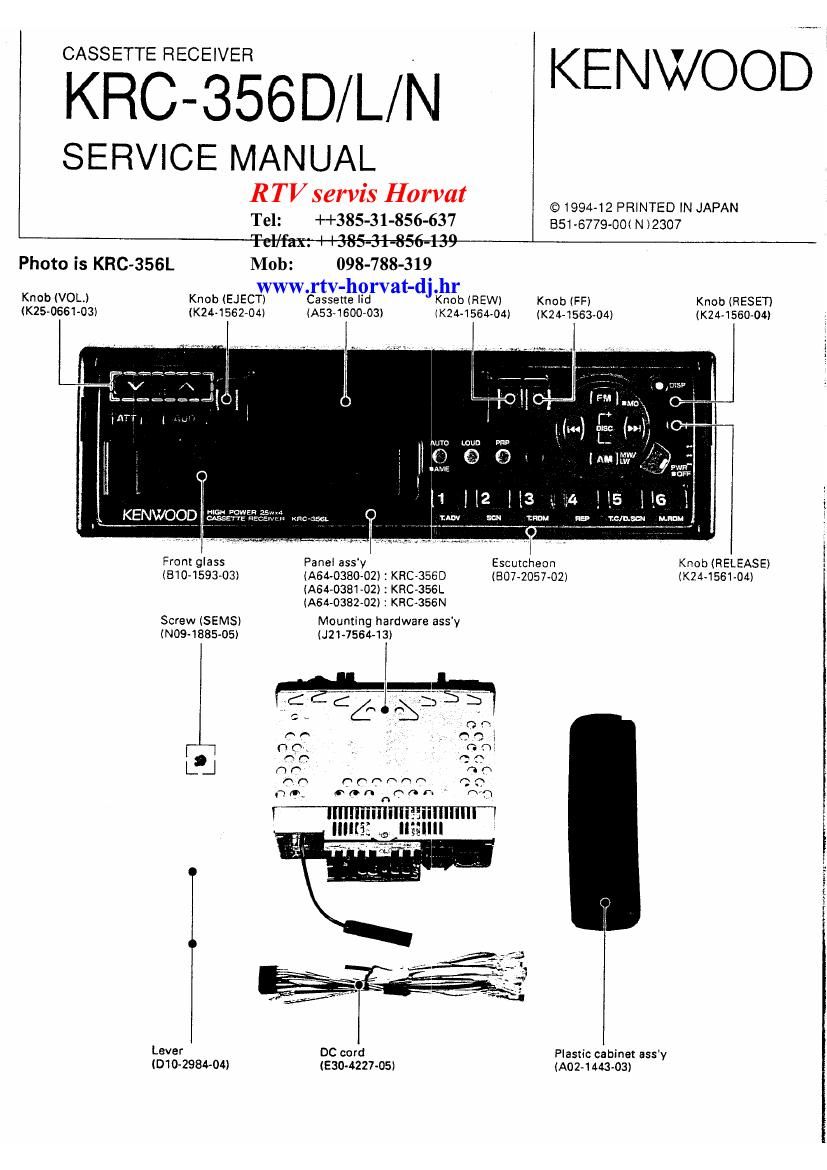
Kenwood KRC 356 N Service Manual

This is the 48 pages manual for Kenwood KRC 356 N Service Manual.
Read or download the pdf for free. If you want to contribute, please mail your pdfs to info@audioservicemanuals.com.

Page: 1 / 48
left right
Kenwood KRC 356 N Service Manual

Extracted text from Kenwood KRC 356 N Service Manual (Ocr-read)


Page 2

KRC-356D/ L/ N

CONTENTS/CUNNEUHONS

CONTENTS

CONNECTIONS .................. ..2
BLOCK DIAGRAM ......

CIRCUIT DESCRIPTION

DISASSEMBLY FOR REPAIR (MECHANISM) ....... 10

MECHANISM OPERATION DESCRIPTION ..
ADJUSTMENT....

...II

CONNECTIONS

circled numbers indicate the procedures

described in the Installation Procedure Output
non: [m SEQ)
C

Kenwood disc changer

To connect the disc
changer, consult your

disc changer manual. (optional)
Rear left out:
(KHC-3560/3
Rear L- Power amplifier
sneakers [- (Sald separately)
Rear right
(1310356
Power control input 4"{2

..£fl L

PC BOARD (COMPONENT SIDE VIEW)
PC BOARD (FOIL SIDE VIEW)
SCHEMATIC DIAGRAM ............
EXPLODED VIEW (MECHANISM)
EXPLODED VIEW (UNIT) .
PARTS LIST .............
SPECIFICATIONS

...BACK COVER

Changer connection cable (Supplied
With the Kenwood disc changer)


FIWAM antenna input

disc changer control

)ut(Whitel
SEUIISSN only)

PG)
i=®

output (Red)
DB56L/356N only)

Power/Fun automatic newer antenna

CDNIOI cable (Blue/White) Wiring

harness
(Accessory)


133:3," key (1):: 9 Car fuse box
ca, w ACC _ ® lgnrtsnn cable (Rad) @
310:: _ © Battery cable (Vellow) @
I33? ; Ground cable (Black) 6 (To car chassis)
Battery Q 6 ©
W WARNING)

( . CAUTION

When two speakers are connected to the
system, be sure to connect both of them to the
Iron! output or rear output. In other words. do
not connect the positivn connector of the loft
speaker to the front cutout and the negative
connector to the rear output.

war:
(a
speak (3

' White

@9: __ Gray/Black
:m[D{::wvm emu
speaker @0" Gray

:2 Green/Black
_:' Green

C _ Purple/Black
_:' " Purpln

To prevent fire when the ignition cable (Red) or
battery cable (Yellow) is snortcircuitad by coming
into contact with the vehicle chassis (ground). only
connect the power supply after making the fuse box 1,
connections.

DHEQ) _
[1142252


Whi te/Black
Front lefi:
sneaker

Front right
age: ker

' Gray

A Green/8'36)!
Rear leIt Egg-3h: -
93km @@ " Green

7 FurnleIBaCk
Rear right gage;
snooker @® _

Page 9

KRC-356D/L/N7

CIRCUIT DESCRIPTION

Audio processor part

Features :

Input multiplexer

' Differential CD stereo input.

- Cassette stereo input.

0 FM Stereo input from stereo decoder.
0 AM input .

Mono or stereo mode (Programmable)
~ Beep input (Only in AM mono mode)
- Telephone differential mono input
- Gain programmable in 3 x 3.75dB steps.

Loudness
- Fully programmable.
- 15 x1.25dB steps.

Volume control

- 1.25dB coarse attenuator.

- 0.31d8 fine attenuators.

- Max gain 20d8.

- Max attenuation 59.69dB (Plus loudness).

Bass control

0 1'7 x 2dB steps.

a 2nd order symmetrical or non symmetrical frequency
response (Programmable).

Treble control
0 :7 x 2dB steps.

Speaker control

- 4 independent speaker control in 1.25dB steps
0 Control range 37.5dB.

- Independent speaker mute.

Mute functions

- Direct mute.

- Zero crossing mute with programmable threshold.
- Soft mute with external defined slope.

Pause detector
' Programmable threshold.
0 Delay time defined by an external capacitor.

Stereo decoder part

Features:

. Integrated 19kHz notch filter for pilot cancellation.

0 On chip filter for pilot detector and PLL.

- Adjustment free voltage control LED oscillator.

- Automatic pilot dependent mono/stereo switching.

Very high inter modulation and inter reference sup-
pression.

- IC bus controlled (STD off, forced mono, stereo).

- High out control.

- Stereo blend.

Noise blanker part

Features:

. internal 2nd order high-pass filter.

0 Noise rectifier output for signal quality detection.

- Programmable trigger threshold.

- Trigger threshold dependent on high frequency
norse.

- Blanking time programmable by external capacitor.

- Very low offset current during hold time due to

- OPAMPS with MOS inputs.

- Level input for additional spike detection on field
strength.

Page 12

KRC-356D/L/N
MECHANISM OPERATION DESCRIPTION

LOADING
1. Insert a cassette tape ( 0).

The pack slider (50) presses the lever (49) (0 ).
The lever (49) rotates and the push plate (58) lock
releases. The push plate is pulled by spring (59)
and moves forward ( 9).

9.

4. The holder (48) lowers following the groove in the
push plate (58) l 0).

5. The slide switch (51) is pressed by the push plate
(58) and turns ON. When 51 turns ON, current is
supplied to the motor (M1) ( 6).

12