Kenwood KRA 47 Service Manual

This is the 32 pages manual for Kenwood KRA 47 Service Manual.
Read or download the pdf for free. If you want to contribute, please mail your pdfs to info@audioservicemanuals.com.

Page: 1 / 32
left right
Kenwood KRA 47 Service Manual

Extracted text from Kenwood KRA 47 Service Manual (Ocr-read)


Page 1

AM-FM STEREO RECEIVER . .
KR-A47 KE'W

SERVICE MANUAL

(:9 1988-3 PRINTED IN JAPAN
8514348600 (G) 2627

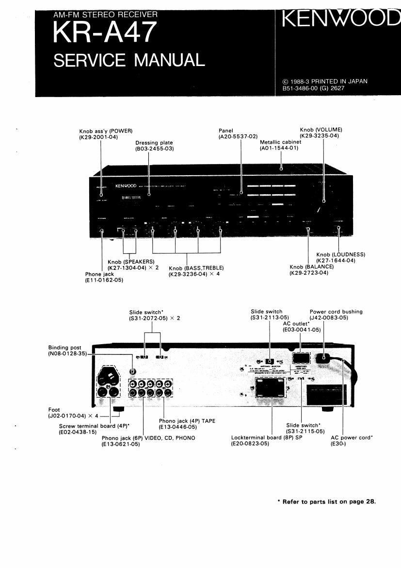
Knob ass'y (POWER) Panel Knob (VOLUME)
(K29-2001-04) (A20»5537-02) (K29-3235-O4)
Dressing plate Metallic cabinet
(803»2455-03) (A01<1544-01)

Knob (LOUDNESS)

Knob (SPEAKERS) (KN-164404)
(K27-1304-04) X 2 Knob (BASS,TREBLE) Knob (BALANCE)
Phone lack (K29-3236-O4) x 4 (K29-2723-04)

(E11-0162-05)

Slide swich' Slide switch Power cord bushing
(831-2072-05) X 2 (531-21 1305) (J42-0083~05)
AC outlet
(503-0041-05)
Binding post
(NOB-012835)

Foot
(J02-0170-04) X 4 - 3 I

Phono jack (4P) TAPE

Screw terminal board (4Pl' (5134344505) Slide switch'

(E02-0438-15l (831-2115-05)
Phono jack (6P) VIDEO, CD, PHONO Lockterminal board (SF) SF AC power cord'
(E13-0621-05) (E20-0823-05) (E30-)

' Refer to parts list on page 28.

Page 2

u A

CONTENTS

DISASSEMBLY FOR REPAIR .. 2
BLOCK 8t LEVEL DIAGRAM 3
CIRCUIT DESCRIPTION 4

ADJUSTMENT .............

REGLAGE .t

ABGLEICH

PC BOARD 19
SCHEMATIC DIAGRAM t. 23
EXPLODED VIEW 27
PARTS LIST ..................... 28
SPECIFICATIONS Back cover

DISASSEMBLY FDR REPAIR

(Remove the metallic cabinet before performing the
following operations.)

I. Remove the 3 screws fixing the front panel to the
chassis (0).

2V Disengage the 2 claws of the sub panel from the
chassis (9).

3. Remove the front paneI together with the sub panel
in the direction of the arrow (9).

4. Pull out the 2 knobs of the VOLUME and BALANCE
from the shafts, and remove the hex. nut from the
VOLUME shaft (0).

5, When instahing the front panel, pay attention to the
mounting posmon related to the chassis (e).

6. Remove the 3 screws fixing the Receiver Unit (XI 4-
2 I 80-I O) (8/8) to the sub paneI (e).
7. Remove the Receiver Unit (XI 4-) (8/8) In the direction
of the arrow (0).
8. Remove the screw fixing the Receiver Unit (XI 4,)
(H/8) to the sub paneI I0)-
9. Remove the Receiver Unit (XI 4-) (H/8) in the direction
of the arrow (9).
10. Remove the 5 screws fixing the Receiver Unit (XI4-)
(6/8) to the sub panel (@I
I I. Disengage the 4 claws (upper side: 2, lower side: 2)
of the sub paneI which retain the Receiver Unit (XI 4-)
((3/8) (0).
12. Remove the Receiver Unit (XI 4-) (G/8) in the direction
oi the arrow (@).
13 Remove the 2 screws fixing the multiple push switch
(S4) to the sub panel (®).
14 Remove the multiple push switch (S4) together with
the Receiver Unit (X14-)(C/8) in the direction of the
arrow (0).

Page 5

IC2: CX79ZSB
Frequency Synthesizer PLL lC

Block diagram and terminal configuration diagram

V55 AMI V00 FMI TVI BO A0


l/2

SWALLOW i/A , I/5 M
P RESCALER

COUNTER PRESCALER
£9 MAIN DIVIDER
_° (16-511' , PROGRAMMABLE)

UP/ DOWN COUNTER
(IE-SIT)
PCB l-pi PHASE
VOLTAGE SHIFT REGISTER
GENERATOR rzo-am COMPARATOR
AT H
ITS-SIT)
TIMING
REFERENCE DIVIDER
C°NTR°LLER 14- 3.1T PROGRAMMABLE
1 \f \f FV \_/
V53 CLK LAT DIN XI XO PD
Terminal description
Terminal No. Symbol Terminal Description
I Vaa PCB terminal (Connect a 0.01 uF capacrtor between the GND),
2 CLK Input terminal for the clock used for 20ehit serial data input (Shifted at the rise).
Input terminal for the shift register Input data latch signal (shifted at the rise) and, at the same time, for
3 LAT the Up/Down clock (status changed at the 38).
Data input terminal, also the Up/Down mode swrtching terminal (Up mode wrth "H" level, Down mode
4 DIN ,. ..
wrth L level).
5 X1 Connection terminals (or the reference Signal generator X'tal oscillator.
6 x0 (Max. 13 MHz, standard 4.0 MHz)
7 PD Phase comparator output terminal (3state).
8 A0 External control Signal output terminal/Unlock signal output terminal (E/E MOS push-pull)
9 80 External Control signal output terminal/data check terminal (E/E MOS pushepull).
10 TVI High-frequency signal input terminal (300 MHZ or 350 MHz max.) With 1/2 prescaler.
11 FMI High-frequency signal input terminal(150 MHZ or 180 MHz max.)
12 VDD Power supply (+5V).
13 AMI High-frequency srgnal input terminal (40 MHz or 50 MHz max).
14 V55 Grounding terminal.