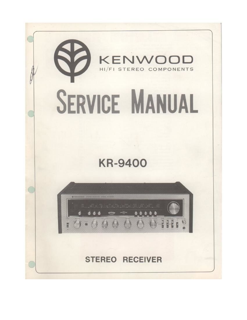
Kenwood KR 9400 Service Manual

This is the 31 pages manual for Kenwood KR 9400 Service Manual.
Read or download the pdf for free. If you want to contribute, please mail your pdfs to info@audioservicemanuals.com.

Page: 1 / 31
left right
Kenwood KR 9400 Service Manual

Extracted text from Kenwood KR 9400 Service Manual (Ocr-read)


Page 1

KENWOOD

Hl/Fl STEREO COMPONENTS

SERVICE MANUAL

KR-94OO

STEREO RECEIVER

Page 8

BLOCK DIAGRAM/CIRCUIT DESCRIPTIONS

.- my

. My

wow i

wow :

m

m

cm

a

unvmm
- Ill M
{Iowan-m

MULTIPATN METER

The multipath meter is used to monitor antenna
multipath components which affect FM reception. It
detects multipath components or AM components from
lF stage through D136 and Db7.

The multipath components thus detected are fed to
xiii-1880710 consisting of 051, L51, 052, L52 and 053
and then rectified by negative voltage doubler rectifier
composed of 031 and D52.

This voltage is mixed with the signal meter input to
deflect the meter pointer The multipath components
exist in 38kHz band, whid't vitally affect the stereo
demodulation.

In practical application of the multipath meter, the
antenna should be set to a position where the variation
of meter reading is minimum with respect to the reading
on the 8 meter (meter reading is low when multipatn
components are large)

MULTlPATH (X13-1880-10)
_T.'2'Eo_ -_____


5°) its.


"mu
m L£VEL

ovum mu: autumn-on

mum
In A an an n my
in: A mm 9.. a m

.
axe-=-
. a

_4 nun mu:

a n
rwrscnw

DEVIATION METER

This meter checks the modulation degree (deviation) of
broadcast signal.

The circuit system oi this meter is such that the
composite signal detected is amplified by DC amplifier
[lC used) to provide excellent transient response.

The meter pointer indicates full scale (100%) at 67,5kHz
deviation, 100% modulation for FM stereo or at 75kHz
deviation, 100% modulation for FM mono,

SOUND INJECTION

This circuit has a function to edit tape. It permits
mixing recording when used with the tape monitor
switch and the dubbing switcht Mixing level can be
controlled as desired. Both the mixing source output
and the mixed source output an be checked through
the speaker output with MONlTOFi switch,

The mixing level control functionsat the ON position of
the sound injection switch, controlling the mixing gain
of the selector sources For normal tape monitor or
dubbing, the iniection snitch should beset to OFF.

TAPE SOUND

Salli? WEE INJSEVEYYlgfl sputter: ouwur REC figeguwur
A TAPEAA

SOURCE Ara SELECT" TAPE-ABSELLCTCM
B 0N TAPEAII ELEUYDI
A TME-BKSELECYOR

SOURCE 341 SELW TAPES E SE LECTOW
a nun

RELATIoN 0F swrrcues AND ouwur