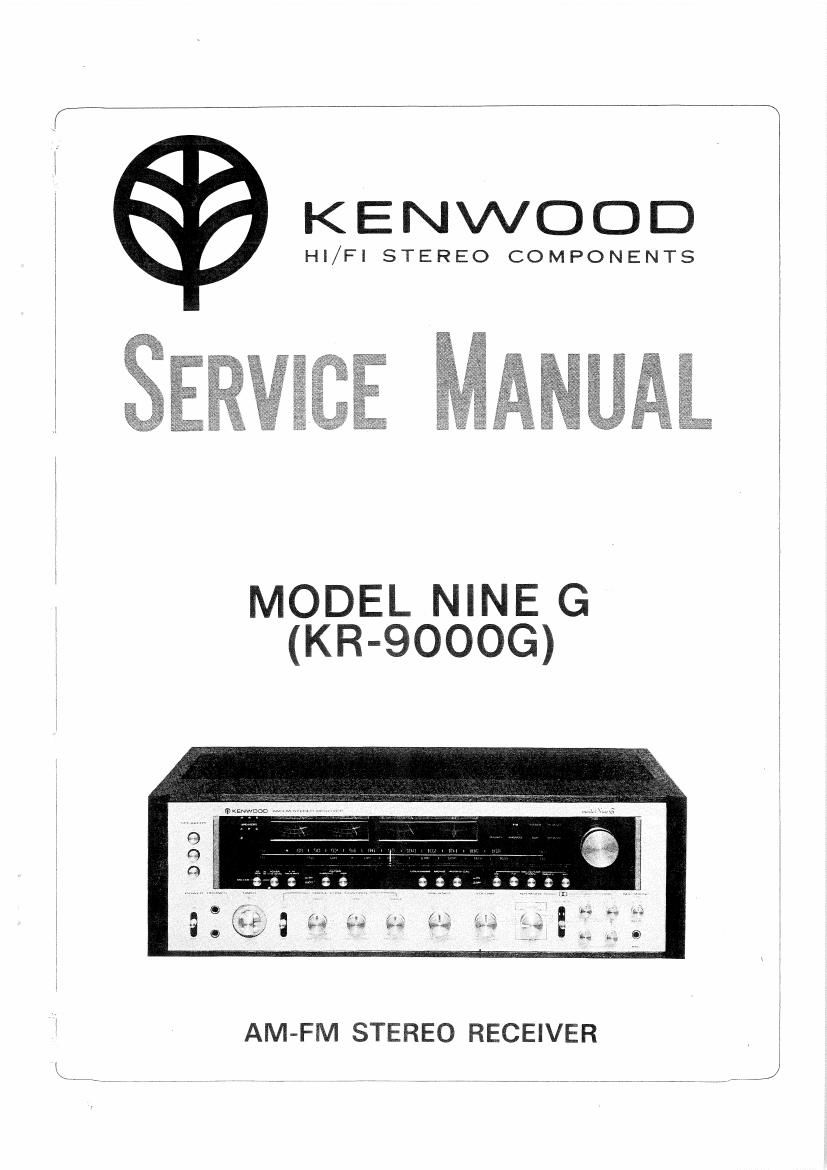
Kenwood KR 9000 G Service Manual

This is the 16 pages manual for Kenwood KR 9000 G Service Manual.
Read or download the pdf for free. If you want to contribute, please mail your pdfs to info@audioservicemanuals.com.

Page: 1 / 16
left right
Kenwood KR 9000 G Service Manual

Extracted text from Kenwood KR 9000 G Service Manual (Ocr-read)


Page 2

W

CONTENTS
EXTERNAL VIEW .............................................................................................. a
INTERNAL VIEw ........... ' .................................................................................... I . 3
DISASSEMBLY FOR REPAIR ........................................................................... 4
DIAL CORD STRINGING ................................. ' ............................................... 5
BLOCK DIAGRAM ............................................................................................. s
LEVEL DIAGRAM ............................................................................................ 6
ADJUSTMENT .................................................................................................. 5
Pc BOARD. 8
SCHEMATIC DIAGRAM ..... 11
SPECIFICATIONS ............................................................................ , ........... 11
PARTS LIST ....................................................................................................... 12

Doiby and the doubberD symbm are the trade mark of Dolby Laboramncs In:

Page 5

DISASSEMBLY FOR REPAIR/DIAL CORD STRINGING

TIMER TONE AMP

TONE amp PCB assy
(X1111510-80)


Sub panel

Timer switch
(551-1041-05)

mounting
hardware
Knob
l (Er-Tap)

DOLBY AMP

Dolby PC board assy
(X14»1110~EOHA/2)

M3 X 5 ®

Brazier tap tight screw (Br-Tap) /
(NF/$00846)

Dolby PC board assy

(X14-1110-80] (3/2)

Flat head tap tight screw.
(NEE-300646)

.Afis...

KENW-05370/ DRUCK3

DIAL CORD STRINGING

1. Fully open the variable capacitor.

2. Set the dial pulley as illustrated. and fix.it with a screw.

3. Te the end of the dial cord and the dial spring, giving a

margin of about 10 cm,

4, Hook the spring on the boss.

5. Dress the dial cord in the direction of 1" to ,2 and

wind it 2 turns around the dial shaft clockwise.

6. Dress the dial cord in the direction of "3" through 27
and wind it one and half turns around the dial pulley
starting from its lower side.

. Tie the dial cord rigidly with the margln cord (about 10
cm, described in 3. above) without permittting any slack.
8. Cut 01f the unnecessary part of the cord. and release the

dial spring from the boss.
9. Fully close the variable capacitor,

10. Mount the dial pointer in position as illustrated. This

setting should be checked by receiving a suitable broad-
cast station actually.

\1

Dial pulley (D15-0171-13l


Variable capacitor
(001-021 1~05)

Small pulley

Dial shaft ass'y
(D20-0142-03)

Dial pointer
(3210023704)

(D15-0172-04}