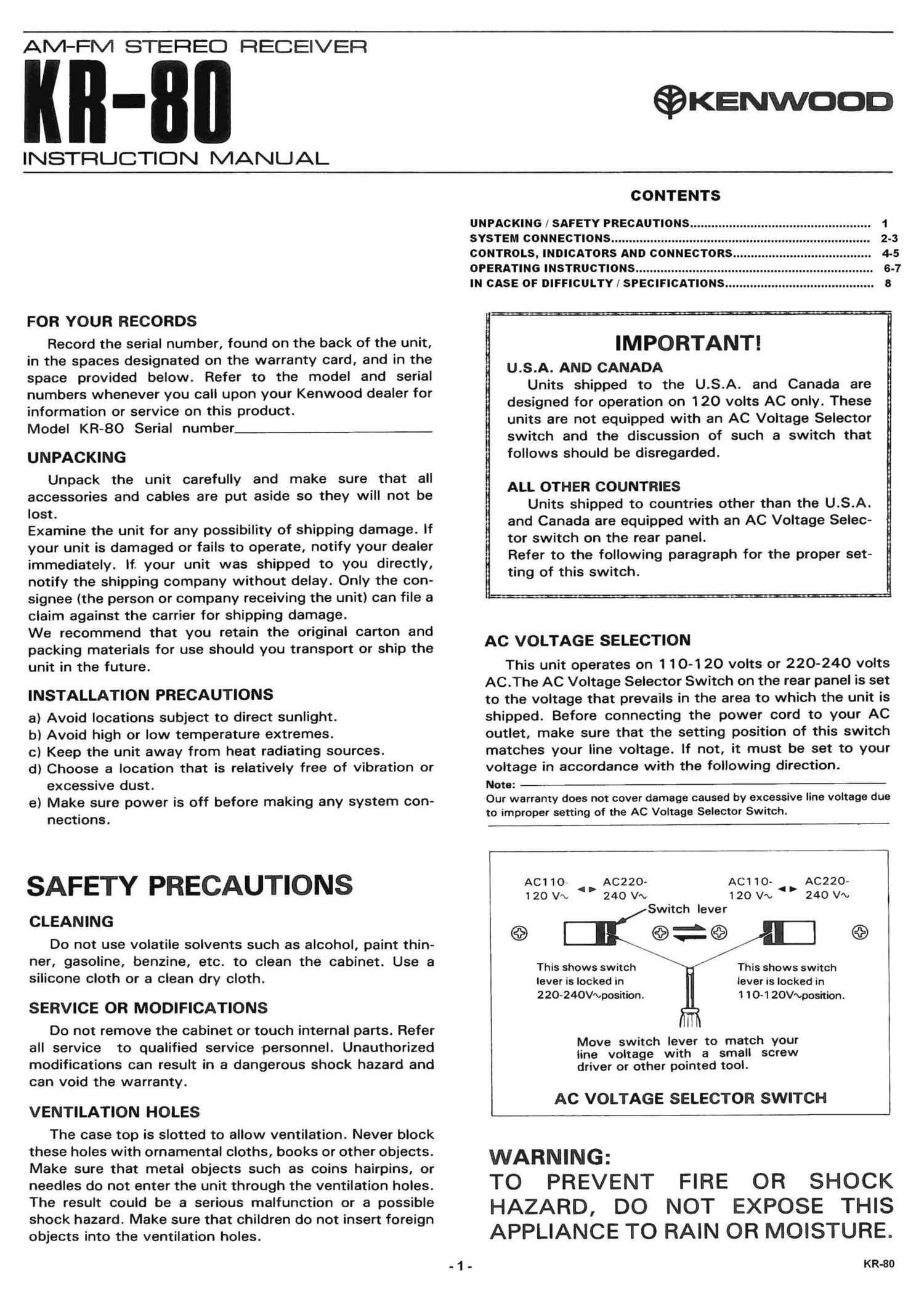
Kenwood KR 80 Owners Manual

This is the 8 pages manual for Kenwood KR 80 Owners Manual.
Read or download the pdf for free. If you want to contribute, please mail your pdfs to info@audioservicemanuals.com.

Page: 1 / 8
left right
Kenwood KR 80 Owners Manual

Extracted text from Kenwood KR 80 Owners Manual (Ocr-read)


Page 1

AM-FM STEREO RECEIVER

INSTRUCTION MANUAL

©KENwoon

FOR YOUR RECORDS

Record the serial number, found on the back of the unit,
in the spaces designated on the warranty card, and in the
space provided below. Refer to the model and serial
numbers whenever you call upon your Kenwood dealer for
information or service on this product.

Model KR-80 Serial number

UNPACKING

Unpack the unit carefully and make sure that all
accessories and cables are put aside so they will not be
lost.

Examine the unit for any possibility of shipping damage. If
your unit is damaged or fails to operate, notify your dealer
immediately. If. your unit was shipped to you directly,
notify the shipping company without delay. Only the con-
signee (the person or company receiving the unit) can file a
claim against the carrier for shipping damage.

We recommend that you retain the original carton and
packing materials for use should you transport or ship the
unit in the future.

INSTALLATION PRECAUTIONS

8) Avoid locations subject to direct sunlight.

b) Avoid high or low temperature extremes.

0) Keep the unit away from heat radiating sources.

d) Choose a location that is relatively free of vibration or
excessive dust.

e) Make sure power is off before making any system con-
nections.

SAFETY PRECAUTIONS

CLEANING

Do not use volatile solvents such as alcohol, paint thin-
ner, gasoline, benzine, etc. to clean the cabinet. Use a
silicone cloth or a clean dry cloth.

SERVICE OR MODIFICATIONS

Do not remove the cabinet or touch internal parts. Refer
all service to qualified service personnel. Unauthorized
modifications can result in a dangerous shock hazard and
can void the warranty.

VENTILATION HOLES

The case top is slotted to allow ventilation. Never block
these holes with ornamental cloths, books or other objects.
Make sure that metal objects such as coins hairpins, or
needles do not enter the unit through the ventilation holes.
The result could be a serious malfunction or a possible
shock hazard. Make sure that children do not insert foreign
objects into the ventilation holes.

fl I _ -

CONTENTS

UNPACKING / SAFETY PRECAUTIONS ...................................................

1

SYSTEM CONNECTIONS ......................................................................... 2-3
CONTROLS, INDICATORS AND CONNECTORS ....................................... 4-5
OPERATING INSTRUCTIONS ................................................................... 6-7
IN CASE OF DIFFICULTY / SPECIFICATIONS .......................................... 8

IMPORTANT!

U.S.A. AND CANADA

Units shipped to the U.S.A. and Canada are
designed for operation on 120 volts AC only. These
units are not equipped with an AC Voltage Selector
switch and the discussion of such a switch that
follows should be disregarded.

ALL OTHER COUNTRIES

Units shipped to countries other than the U.S.A.
and Canada are equipped with an AC Voltage Selec-
tor switch on the rear panel.
Refer to the following paragraph for the proper set-
ting of this switch.

AC VOLTAGE SELECTION

This unit operates on 1 10-120 volts or 220-240 volts
AC.The AC Voltage Selector Switch on the rear panel is set
to the voltage that prevails in the area to which the unit is
shipped. Before connecting the power cord to your AC
outlet, make sure that the setting position of this switch
matches your line voltage. If not, it must be set to your
voltage in accordance with the following direction.

Note:
Our warranty does not cover damage caused by excessive line voltage due
to improper setting of the AC Voltage Selector Switch.

AC220-
240 VV

AC1 10-
120 Vm

AC220-
240 VI»

AC1 10-
1 20 V'\,
Switch lever


This shows switch
lever is locked in
1 10-1 20V~position.

This shows switch
lever is locked in
220-240Vmposition.

Move switch lever to match your
line voltage with a small screw
driver or other pointed tool.

AC VOLTAGE SELECTOR SWITCH

WARNING:

TO PREVENT FIRE OR SHOCK
HAZARD, DO NOT EXPOSE THIS
APPLIANCE TO RAIN OR MOISTURE.

KR-80

Page 2

SYSTEM CONNECTIONS

FM INDOOR ANTENNA

O

o 1 ®

FM OUTDOOR ANTENNA

L
LINE IN

L


LINE OUT

LINE OUT

SPEAKER SYSTEM A
Right

" @IIII

If

111114.111

Left

11 IIIII

.1 1111911111111111111111111

I, If
11,; -4 .\

iIIIIIIIIIIIllmu 111111 nl/IIIIIIIIIII1

-+ 4»

AM OUTDOOR
ANTENNA

G

SWIT CHEO UNSWITCHED

IOOW MAX. 200' MAI. l

[Fl]

U

-

+.-/ +

SPEAKERS HAUT- PARLEURS I4~ IGQI

TO AC OUTLET

LlNElN
_. - 5'" - _, - EEI . 11111 I. 11.. 1.111111
11 iiiiii m G a I Ill in: g 1Q iJ IIIZNJIIIIIEII III .. 11111 MIMI
- Left Right
TURNTABLE TAPE DECK B TAPE DECK A SPEAKER SYSTEM B
SPEAKERS TAPE DECKS

lf only one set of speakers is to be connected, make
connections to the terminals marked SPEAKERS A. Con-
nect the speakers to the L and Eterminals in accordance
with the location selected for each speaker. To ensure cor-
rect speaker phasing, observe polarity marks; connect ter-
minals marked (+) on the receiver to similarly-marked
speaker terminals. Do the same for receiver and speaker
terminals marked with a minus sign. Reversal of speaker
leads will result in loss of bass tones and poor stereo
separation.

If a second set of speakers is to be used make connec-
tions at the set of terminals, marked B.

It is recommended that the tips of the speaker leads be
soldered, or the strands of individual leads be twisted
together to eliminate any possibility of short-circuits form-
ing in the speaker connecting network.

Note:
If a single pair of speakers is to be used, each speaker must be rated at
4 ohms or more.

10:71!» .
r I Remove insulation
1 from lead tip.

3/8

W Twist wire tightly,
and solder.

Loosen the

screw wire screw

Speaker Lead Connection

Insert the Tighten the

If only one tape deck is to be connected to the system it
is recommended that it be connected to the jacks marked
TAPE B.

Tape deck input and output cables are normally ter-
minated with phono plugs.

Playback

Plug the left and right output cables of the tape deck
into the and El TAPE B PLAY jacks.
Record

Plug the left and right input cables of the tape deck into
the L and E'TAPE B REC jacks.
Second Tape Deck

Plug the input and output cables from the second tape
deck into the REC and PLAY jacks marked TAPE A.

TURNTABLES

Your stereo turntable has two audio cables that are ter-
minated with phono plugs. Plug the left channel plug into
the L and the right channel plug into the R PHONO input
jacks.

If the turntable has a ground wire, connect it to this
units GND terminal to avoid hum.

KR-80