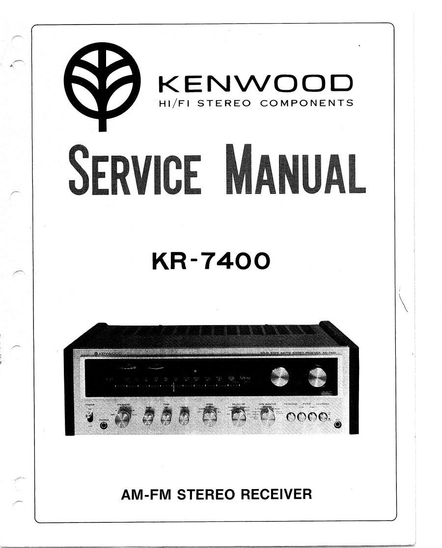
Kenwood KR 7400 Service Manual

This is the 36 pages manual for Kenwood KR 7400 Service Manual.
Read or download the pdf for free. If you want to contribute, please mail your pdfs to info@audioservicemanuals.com.

Page: 1 / 36
left right
Kenwood KR 7400 Service Manual

Extracted text from Kenwood KR 7400 Service Manual (Ocr-read)


Page 2

CONTENTS

EXTERNALVIEW .................................. 3
TOP & BOTTOM VIEW .......................................... 4
DISASSEMBLYICORD STRINGING ................. . . . . . . . . . . ....... 5
BLOCKDIAGRAM........... ................... . .............. 6
CIRCUITDESCRIPTION................ ..................... 7~9
ADJUSTMENTS ........................................... 10, 11
PACKING ................................................... 12
PARTS LIST
MODIFICATIONS . . ................................... 13
TOTAL .............. I . ............................. 14
AUDIO SECTION ASS'Y ..... 14
TUNER SECTION ASS'Y I I . ..... 15
POWER SUPPLY (X00-1430-10I ................................... 15
RF (XO1-1160-10) ........................................... 17
IF (X02-1050-11) ......................................... 18~20
MPX IXO4-1040-10I .......................................... 21
MAIN AMP (X07-1270-10) ..................................... 22, 23
PREAMP 1X08-1270-00) ...................................... 24
TONE AMP (X11-1210-00) ..................................... 25
PUSHBUTTON SWITCH (X13-1BOO-10) .............................. 26
CONNECTION (X13-1810-10I .................................... 26
PC BOARD
POWER SUPPLY ........................................... 27
RF .................................................... 27
IF .................................................... 28
MPX ................................................... 28
MAIN AMP 29
PREAMP 30
TONE AMP 30
PUSHBUTTON SWITCH 31
CONNECTION ............................................. 31
TROUBLESHOOTING ........................................... 32
SEMICONDUCTOR SUBSTITUTIONS AND LEADS ......................... 33
MODIFICATIONS... ...................... ...... 34
SCHEMATICDIAGRAM.. ...................... 35
SPECIFICATIONS......... .................. ....... 36

Page 7

CIRCUIT DESCRIPTION

FM-BF (X01-1160-10I

Two dual-gate MOS FETs are used for RF stage. FET in
the mixing stage, too, are of this type and produces ideal
mixing effects A buffer follows the local oscillator
(OSC) to inject a stable oscillator output into the mixer,
so that the front end is high in both stability and
sensitivity.

FM-IF (X02-1050-11)

The IF circuit consists of three-elements ceramic filters in
two stages, five transistors, one IC, two IFTs, and ratio
detection The trigger circuit for stereo beacon has two
special transistors for differential amplifier and single
lFT stage. The S-meter circuit consists of a transistor and
an [FT stage. FM muting is employed to cut IC bias with
transistor.

Hfflwsizi'l

law 22

FM MPX (X04-1040-10)

The MPX has PLL MPX integrated circuit (Refer to
page 8). Unlike the conventional circuitry by which a
38-kHz switching signal is derived from the 19-kHz pilot
signal contained in the incoming signal, this MPX produces
a very accurate switching signal by error voltage of phase
difference between the incoming signal and VCO (Voltage
Control Oscillator) through a phase locked loop (PLL).
This method does away with the 19, and 38»kHz coil
and SCA filter traps, which are located in the composite
signal path, of the conventional circuitry.

The new circuitry providesimproved phase characteristics
of the signals, and optimizes the phase relationship on
switching as well as the separation characteristics

plum-4241 _________ u
MPX CIRCUIT» | u
I 9, 3 .m M
_ wxy
in: . 4
° l 2 g;
g | e a
s 3
us: |
I | g g
I x 59 I a ,
I 3 .4 m. I § i
R' E 1 D
| ES .1' in mg
x v m ' w"
I 3 i.»
I §
2 E
ism.
aci_2:2scs45maa)
| excumacwoi
Bauxssssuiszon
- -o-

1w;
a ,.___.

PRE AMP.

a» :2scs45inp 5;,
w .izzzscsauo)
,mzzscwini

006,5: zscwm
:- aw,a:2sczaun,oiorzscsasisi

PREAMP CIRCUIT > F-

m wm

A IF CIRCUIT

4 TA7060P
5 +3
CIRCUIT
NON- 2.5m ,, OUT
INVERTING INPUT Ile1I
l 0- Q3 Q4
2 O
lNVERTlNG INPUI
QI
Q2 Q5
0
3 cm)

icaizaassm

PREAMP (X084 270-00)

Metal can sealed monolithic lC is used here This IC
consists of the differential amplifier of the first stage
and emitter followers of next stage, operating to provide
Class A drive and pure complementary output. The circuit
is a wide dynamic range circuit, operating with high input
impedance and low output impedance and drawing two
power supplies, positive and negative, and thus ensures
stabilized equalizer characteristics.

Page 14

TOTAL PARTS LIST

Ref. No. Parts No. Description Remarks
- A01-0240-03 Case
- A13-0088-03 Frame (A)
- A13-0089-03 Frame (B)
~- Alto-01 29-13 Bottom plate
- A48-0018-04 Panel side plate (L)
- A48-DO19-04 Panel side plate (R)
- 301-0088-05 Panel escutcheon
- 810-0148-03 Frontglass
-- 319-0163-12 Color board
- 821-2021-05 Dial pointer
- 342-0009-04 Passed sticker
- 652-0164-00 Schematic diagram
- D21-0361-14 Dial shaft assembly
- D22-0018-05 Shaft coupler
- D23-0048-04 Bearing
- F19-0160-O3 Wooden side board (L)
- F19-0161-03 Wooden side board (R)
- 1:19-0162-14 Blinder
- J02-0049-14 Leg x 4
- J19-0415-03 Frontglass stopper (Top)
- J19-0416-03 Frontglass stopper (Bottom)
- J90-0057-13 Dial pointer rail
- K230164434 Knob (TUNlNG)
- K23-0165-04 Knob (VOLUME)
- K230166414 Knob (BALANCE)
- K23-0167-04 Knob (TAPE MODE, SPEAKERS, MODE, SELECTOR) x 4
- K23-0168-14 Knob (TONE) X 3
- K29-0195-04 Knob (Pushbutton) x 4
- K29-0196-04 Knob (POWE R)
- NOS-012605 Dress screw x 6
- Tao-000205 FM indoor antenna

14