Kenwood KR 1060 VR Service Manual

This is the 48 pages manual for Kenwood KR 1060 VR Service Manual.
Read or download the pdf for free. If you want to contribute, please mail your pdfs to info@audioservicemanuals.com.

Page: 1 / 48
left right
Kenwood KR 1060 VR Service Manual

Extracted text from Kenwood KR 1060 VR Service Manual (Ocr-read)


Page 1

filfiliélififlétw KENWOOD

1060VR/107OVR

S E RV I C E MAN UAL ©1997-6/851-5322-00 (K/K) 3145

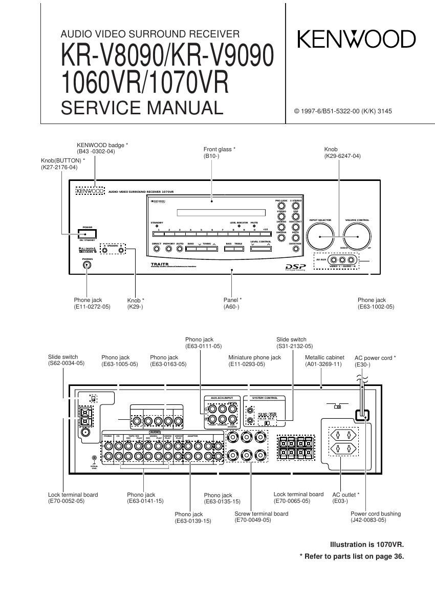
KENWOOD badge ,
(B43 _0302_04) Front glass Knob
(810-) (K29-6247-O4)
Knob(BUTTON) *

(K27-2176-O4)

{Kjgnygchég mummw J

159mm-

Phone jack Knob Panel Phone jack

(E11-0272-05) (K29-) (A60-) (1263-1 002-05)
Phono jack Slide switch
(E63-0111-05) (831-2132-05)
Slide SWilCh Phono jack Phono (ask Miniature phone jack Metallic cabinet AC power cord
(862-0034-05) (E63-1005-05) (E63-0163-05) (E11-0293-05) (A01 6269-1 1) (1230-)

Aux.sn<.mrur 5mm (mum

Lock terminal board Phono jack Phono jack Lock terminal board AC outlet

(E7o-0052-05) (E63-O141-15) (E63-0135-15) (E70-0065-05) (E03-)
Phono jack Screw terminal board Power cord bushing
(E63-0139-15) (E70-OO49-05) (J42-0083-05)

Illustration is 1070VR.
* Refer to parts list on page 36.

Page 2

J COVER(1P" 97.6.22 4:02 PM [I a I] 2
1060VR/1070VR/KR-V8090/KR-V9090

%

CONTENTS / ACCESSORIES

Contents

CONTENTS / ACCESSORIES .................................... 2 WIRING DIAGRAM .................................................... 17

CONTROLS ............................. 3 PC BOARD .......................

DISASSEMBLY FOR REPAIR. 5 SCHEMATIC DIAGRAM

BLOCK DIAGRAM ................... ...6 EXPLODED VIEW ............

CIRCUIT DESCRIPTION ...7 PARTS LIST ............

ADJUSTMENT ................... ,16 SPECIFICATIONS ..

Accessories

f \
FM indoor antenna ........ (1) "AM loop antenna __________ (1) 77777777777777777777 r Remote control unit ...... (1)

(T90-O810-05) (T90-0820-05)

(DEM-999D)

RF DEMODULATOR.....(1)

Q

M,C,T type only

(A70-1118-05): RC-R0805

Loop antenna stand (1)
(J19-3645-05)

Battery cover(A09-O366-08)

AC adapter .................... (1)
(E03-0115-05)

4
i"
M type only

An use model discrepancy table in of remote controller

Remote controller Model name Destination Battery cover
Parts number Type name
A70-1115-05 RC-R0805 1070VR All destinations
KR-V9090
A70-1117-05 RC-R0605 1060VR All destinations 90366438
KR-V8090 C
A70-1118-05 RC-R0606 KR-V8090 T,E,Q

Page 4

1060VR/1070VR/KR-V8090/KR-V9090

CONTROLS

0 POWER key
Use to turn the receiver on and off.
Use in combination with the input selector
(AUDIO, VIDEO, or TV) keys and SHIFT
key to turn various components on and
off.

9 MACRO key
Use in combination with the AUDIO, VID-
E0, or TV keys to execute a series of
commands automatically (MACRO
PLAY).

9 VIDEO selector key
Selects the video inputs (VIDEO 1,
VIDEO 2, VIDEO 3, AV AUX) and sets
the remote to operate the component reg-
istered at the respective input.

0 Multi control keys
Use to operate the selected component.

9 REC key
Use to operate the selected component.

0 TUNING/SKIP key
Use during the setup procedure to specify
various settings. Use to operate the tuner
or selected component.

0 SUBWOOFER key
Use in combination with the VOLUME +/-
keys to adjust the volume of the
subwoofer.

KENWOOD

0 FUNCTION SHIFT key
Use in combination with the numeric keys
to execute alternate commands.

9 Numeric keys

Provide functions identical to those 01 the
original remote supplied with the compo-
nent you are controlling.

To access the functions printed above the
keys, Press within 3 seconds of pressing
the FUNCTION SHIFT key. Function
availability varies for each component.

(9 SHIFT key
Use in combination with the AUDIO and
VIDEO keys to change the remote control
mode without changing the input selector
or in combination with the POWER key to
turn on and off components programmed
into the remote.

at TV selector key
Sets the remote to operate a TV or cable
box (TV 1, TV 2, CABLE). This key does
not change the input selector on the re-
ceiver.

9 AUDIO selector key

Selects the audio inputs (CD, TAPE/MD.
TUNER, PHONO) and sets the remote to
operate the respective KENWOOD audio
component.

If you connect audio components from
KENWOOD and other makers to the
TAPE/MD or CD jacks, you can set the
remote to operate these components by
registering the appropriate setup code at
the respective input.

® GUIDE key
Use to activate the OSD menu functions
of registered components.

0 VOLUME key
Use to adjust the receiver volume.

@ MUTE key
Use to temporarily mute the sound.

Q9 SOUND key
Use to adjust the bass, treble, and input
level.

0 LISTEN MODE key
Use to select the desired surround mode.

0 SETUP key
Use to adjust the surround setup.