Kenwood KMDPS 970 R Service Manual

This is the 23 pages manual for Kenwood KMDPS 970 R Service Manual.
Read or download the pdf for free. If you want to contribute, please mail your pdfs to info@audioservicemanuals.com.

Page: 1 / 23
left right
Kenwood KMDPS 970 R Service Manual

Extracted text from Kenwood KMDPS 970 R Service Manual (Ocr-read)


Page 1

MD RECEIVER

KM D-X91/P897OR
SERVICE MANUAL

KENWOOD

©1999-4.PR|NTED IN JAPAN
85177459-1O(MC)3275

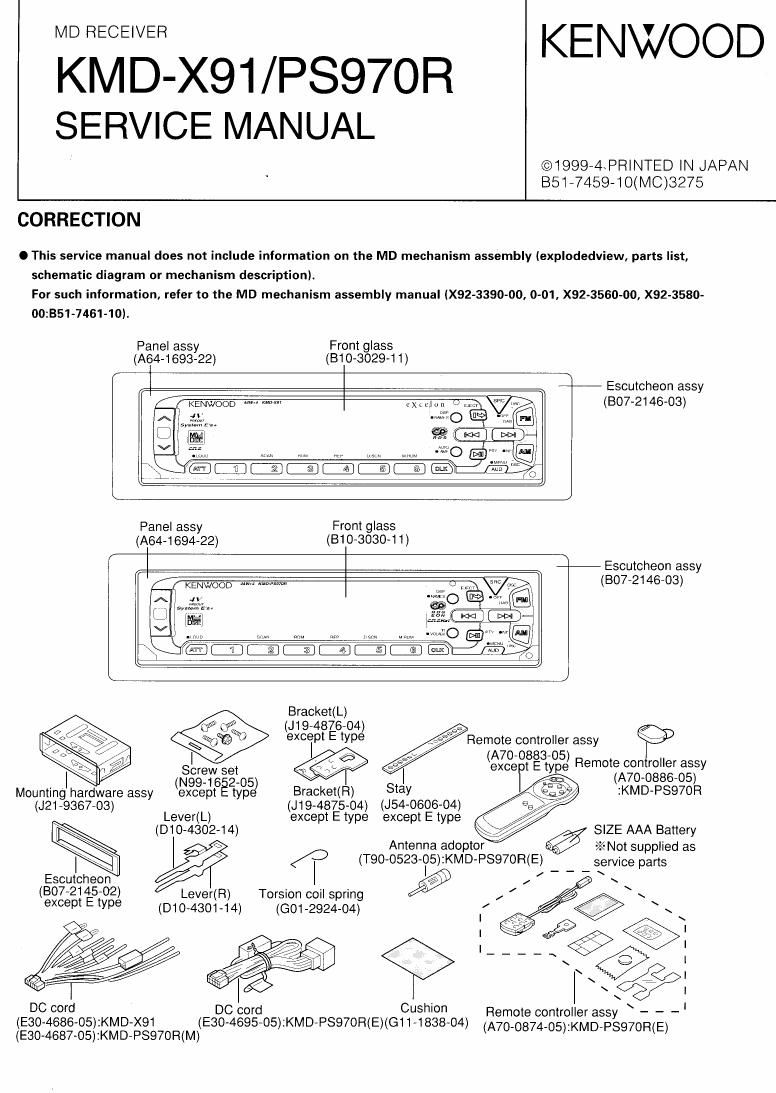
CORRECTION

O This service manual does not include information on the MD mechanism assembly (explodedview, parts list,
schematic diagram or mechanism description).

For such information, refer to the MD mechanism assembly manual (X92-3390-00, 0-01, X92'3560-00, X92-3580-
00:351-7461-10).

Panel assy Front glass
(A64-1693-22) (B10-3029-1 1)

Escutcheon assy
(BO7-2146»03)

Panel assy Front glass
(A64-1694-22) (810-3030-1 1)

Escutcheon assy
(3072146703)
A 5...: misc

me. Q
BE m

a m --:m~»O

Bracket(L)

99 J19- 4876- 04
$452K) Iexcelpt E typ:)

F
Screw set \ I
(N-99 16 2- 05

(A70- 0883 05)
excert tE tyne
Mounting hardware assy (except typ Bracket(R Stay
(J21-\ 9367 03) (J19- -4875- -04) (J54-0606-04)

Lever( L) except E type except E type &
(-D10 4302- 14) SIZE AAA Battery
Antenna adoptor ->: (T90- -0523- -05): KMD- PSQ7OR(E) service parts

EscutIcheon fl
«29 s:
§> -‚¬95

Remote controller assy

Remote controller assy
(A70-0886-05)
:KMD-PSQ70R

E Lever Torsion cIoil spring
(except type (010 4301 14) (GO1--2924 04)

(-BO7 2145- -02)
Cushion

DC cord rd Remote controller assy \ - - -
(E30-4686-05):KMD-X91 (E30- -4695- 05): KMD- PSQ7OR( (E)(G11 1838 04)

- 74» :KM 7P
(E30-4687-05):KMD-PSQ70R(M) (A70 08 05) D SWORIEI

Page 2

KM D-X91 / PSQ70R

CONTENTS

CONTENTS ......................................................................... 2
BLOCK DIAGRAM .............................................................. 2
COMPONENTS DESCRIPTION ...........................
MICROCOMPUTERS TERMINAL DESCRIPTION
ADJUSTMENT ............................... r ..................................... 9

PC BOARD (COMPONENT SIDE VIEW) ............................ 12
PC BOARD (FOIL SIDE VIEW) ............................................ IE
EXPLODED VIEW


PARTS LIST ......
SPECIFICATIONS ............

. ............................ Back cove

BLOCK DIAGRAM

AI
F/E - swsv N5"
come -
050,51 FMfB j
8,139
04 AM+B l02 I05
FM _.
AM E's
MD E VOL
CH ' ICB
EDS OUT 030 I04
,-
S>METER 4 , MUTE DRIVER POWER IC
; Fwa f?
I I O SPDUT
NOISE 1 ,, , ,,
"MP I07 Ion
EZPFIOM SFEANA
AGO OF AMP
MD _.._ a a g ME
053 -
.7 SERVO E AMP
EX. AMP
._ W A CONTROL comnm
012
.7 Busv DIMMER O DIMMER
333; Busv _. '-'
AMUIE ---- m TEL-MUTE
gm
' 029
-‚¬53ch urcom ACC OEr ,- 0 ACC
LOAD
KMD-XQ unIy 0222
CH ANT CON |-~o ANT-CONT
9 BACK up F * as OL2 023-25 h ,
HST Ill N m (b
m <
REELR dgggg 5 E5 :2 mi 029 _ CON -.0 p CON
DATA H 7 2 E E E #\
°¥§82 7 $3228 5) 5% 5,5 2% BU DET, 0 BACK up
DATA 0 SWSV - 3522a
PHI I IC9 SERVO
PHOT SRM SHM '
DET MECHA DRIVER
r ______________ _|
ICI I I014.
Ica 013-20
PANEL .a
u-com

ICSI
04,5657

ALOIE

KM D-XSI
KM D-P597OR