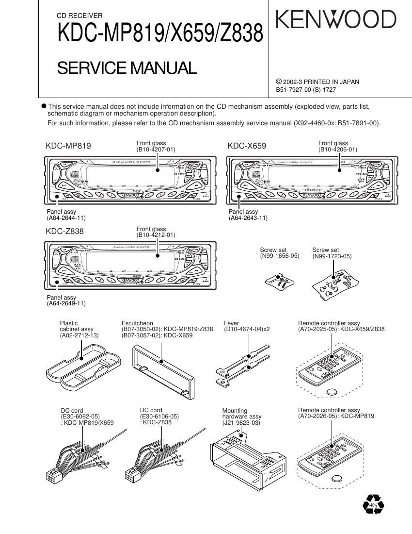
Kenwood KDCX 659 Service Manual

This is the 26 pages manual for Kenwood KDCX 659 Service Manual.
Read or download the pdf for free. If you want to contribute, please mail your pdfs to info@audioservicemanuals.com.

Page: 1 / 26
left right
Kenwood KDCX 659 Service Manual

Extracted text from Kenwood KDCX 659 Service Manual (Ocr-read)


Page 3

KDC-M P819/X659/Z838

COM PONENT DESCRIPTION

0 SWITCH UNIT (X16-168X-XX)

Ref.No. Component Name Application/Function Operaticn/Condition/Compatibility
|C1 TAR5833 FL AVR +3.3V Output
ICZ TC74HC4050AFT Buffer For FL control lines, 5V 6 3.3V logic level shifting
I03 RS-171 Remote sensor IC
IC4 BA3830F BPF IC BPF for the spectrum analyser indicator
ICS UPD703032GFA04 Panel MI-COM.
Q1 DTA144EUA or UN5113 FL & Illumination +B ON/OFF control. When 02's base goes Hi, Q1 is
FL+B SW turned on, and FL+B(45V) line is supplied to the FL indicator and
02 DTCHWUA 0" UN5214 the key illumination circuit.
QS DTA114EUA or UN5111 REMO SW lllggeartn: bgie goes Lo, Q3 is turned on, and PAN5V line is supplied to
Q4 DTC114EUA or UN5211 FL blanking SW When a base goes Hi, Q4 is turned on. and FL indicator is lit.
Q6 DTC114YK or UN2214 SRC key illumination SW When a base goes Hi, OS is turned on, and SRC illumination is lit.
Q7 2804081 V-l converter Current driver for green LEDs
Q8 2804081 V-l converter Current driver for red LEDs
09 DTA114EUA or UN5111 Key illumination Red SW When a base goes Lo, Q9 is turned on, and key illumination Red is lit.
Q10 DTA114EUA or UN5111 Key illumination Green SW When a base goes Lo. 01 O is turned on, and key illumination Green is lit.
0 ELECTRIC UNIT (X25-9240-XX)
Ret.No. Component Name Application/Function Operation/Condition/Compatibility
|C1 UPD703033GFA17 System MI-COM.
ICZ TDA7407 E-VOL.& N.C. MPX
ICS M5237ML AVR IC IC is combined with Q4, and it works as the error detection, the 045 driver.
|C4 TDA7560 Power IC
ics TDA7401 Wiggijumie HPF(Front/Rear output), LPF, Non-Fader switching and volume function
ICB |CL76608|BA DC/DC converter -9V AVR for pre-output amplifier
|C7 TC74HCO2AF Mute logic 2-input NOR x 4
ICB NJM4565M-TE2 Op. amp. Amplifier for the spectrum analyser and generation of Vref. (1 /2Vcc) voltage
|C10 NJM4565M-TE2 Op. amp. Amplifier for the front pre-outputs
|C11 NJM4565M-TE2 Op. amp. Amplifier for the non-fader pre-outputs
|C12 NJM4565M-TE2 Op. amp. Amplifier for the rear pre-outputs
|C16 8-80837ANNP Reset IC When BU 5V voltage is less than 3.7V, lC outputs Lo.
ICZO BA3121 F Isolation amplifier AUX inputs isolation amplifier
ICZ1 BA3129F Switched op.amp. Input switching with AUX inputs and CD inputs
ICZ3 Sl-8050JD MECHA. AVR DC/DC converter, +5V output for CD mechanism adapted for MP3
|C25 BR24C02F-W EEPROM
Q1 ZSD2375 CD servo AVR AVR for CD mechanism servo operation, +7.5V output.
03 ZSA1037K SW 5V While a base goes Lo, SW 5V is supplied to the microprocessor
peripheral clI'CUlIS.
Q4 ZSA2057 A.+8V AVR Q4 is combined with lC3. and it works as the power supply of +8.0V output.
3: EKEZES: Err 33:12:: A.+8V AVR SW When 05's base goes Hi, Q6 is turned on, and A.+8V AVR is working,
Q7 DTA124EUA or UN5112 SW14V When Q8's base goes Hi, Q7 is turned on, and A.+8V AVR, CD servo
Q8 DTC124EUA or UN5212 AVR and A.+10V AVR are working.
For PAN5V on/off switching. When a base goes Lo with panel attached
09 2831427 PANSV SW to the set. Q9 is turned on. and PAN5V is supplied to the panel.
g1? 3:25:32: FL/lllumination AVR When Q11's base goes Hi, AVR outputs +9V.
Q12 DTC124EUA or UN5212 . . When Q12's base goes Hi, Q13 is turned on, and FL/lllumination AVR
013 DTA124EUA or UN5112 FU'llumm'O AVR SW is working.
Q14 DTA123JK or KRA1OSS EXT. AMP CON. SW When a base goes Lo, Q14 is turned on. and control pulse signal is outputted.
Q15 DTC144EUA or UN5213 Dimmer detection SW When vehicle small lamps turn on, Q15's base goes Hi, and it is turned on.
$13 3:33;? A.+10V AVR When Q17's base goes Hi. AVR outputs +1ov.