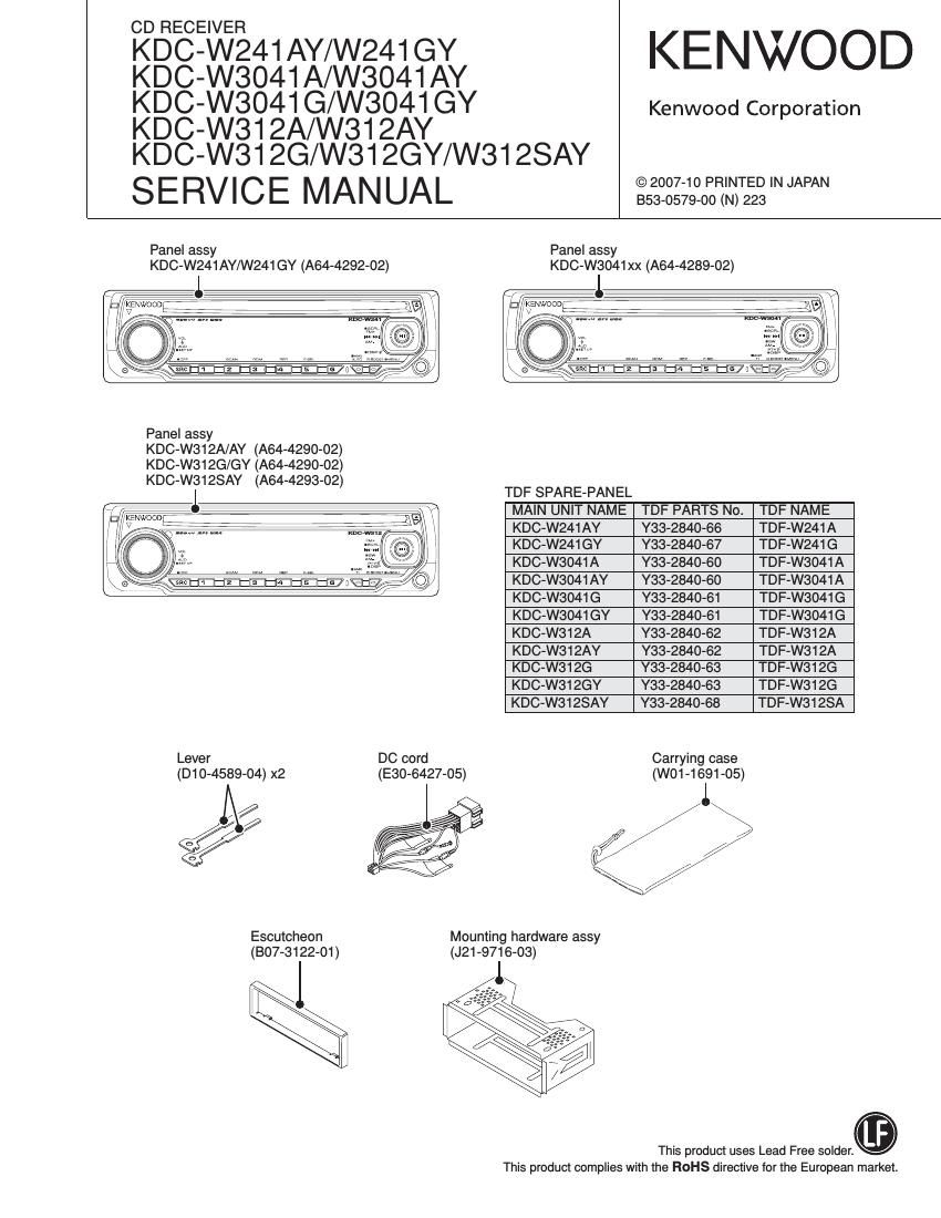
Kenwood KDCW 3041 GY Service Manual

This is the 40 pages manual for Kenwood KDCW 3041 GY Service Manual.
Read or download the pdf for free. If you want to contribute, please mail your pdfs to info@audioservicemanuals.com.

Page: 1 / 40
left right
Kenwood KDCW 3041 GY Service Manual

Extracted text from Kenwood KDCW 3041 GY Service Manual (Ocr-read)


Page 6

KDC-W241AY/W241GY/W3041A/W3041AY/W3041G
/W3041GY/W312A/W312AY/W312G/W312GY/W3l ZSAY

MICROCOMPUTERS TERMINAL DESCRIPTION

Pin No. Pin Name IIO Application Truthllzllaelue Processing Operation Description

43 PON CD 0 CD mechanism power supply control H: Power ON

44 CD LOEJ {/0 CD motor control (1) Refer to the truth value table

45 CD MOTOR l/O CD motor control (1) Refer to the truth value table

46 VFD CE 0 VFD control request

47 CD DRIVEMUTE 0 Motor driver mute output

48 CD CCE 0 CD mechanism chip enable

49 NC - Not used

50 CD MRST 0 CD mechanism p-com reset H: Normal, L: Reset

51 ~53 NC - Not used Output L fixed

54 CD MUTE | CD mute request L: Mute request

55 CD DISC12 SW | 12cm disc detection Pull-up (B.U.)

56 ROTARY COW | VOL key input Detects pulse width

57 ROTARY CW | VOL key input Detects pulse width

58~61 NC - Not used Output L fixed

62 VCCZ -

63 NC - Not used Output L fixed

64 V88 -

65 NC - Not used

66 TUN IFC OUT I Front-end IFC-OUT input H: Station tound, L: No station

67 PON EXT GND l/O ICZ external input quick charge control :igjhlizzli33'300'::{iii/Ifsngjgigsztlffoitfi

68 MUTE l/O Mute L: Mute OFF, Hi-Z: Mute ON

69 ANALOG CON 0 AUX/LX audio switching 22;;St?£:f£éi;§;::::::ei firsmu "we

70 LX RST O Forced reset to slave unit H: Reset, L: Normal

71 LX CON 0 Start-up request to slave unit H: Slave unit ON, L: Slave unit OFF

72 LX MUTE | Mute request from slave unit H: Mute ON, L: Mute OFF

73 LX FlEQ M 0 Communication request to slave unit

74 NC - Not used

75 LX FlEQ S | Communication request from slave unit Pull-down (GND)

76 PWIC SVR O SVR discharging circuit 2:323d5:£::af;:cpeomeernflfF and momentary

77 PWIC STBY 0 Power IC standby control Power ON: H, Power OFF: L

78 PWIC MUTE 0 Power lC mute STANDBY source/Momentary power down: L,
TEL mute: L

79 m | ACC power supply detection ACC found: L, No ACC: H
BU found: L, No BU/Momentary power down: H

80 BU DET | Detection of momentary power down (Operates after less than 4ms after momentary
power down is detected)

81~83 NC 0 Not used Output L fixed

84 TUN SMETEFt | S-meter input

Page 7

KDC-W24i AY/W24i GY/W304i A/W304i AY/W3041 G

/W304iGY/W312A/W312AY/W312G/W312GY/W312SAY

MICROCOMPUTERS TERMINAL DESCRIPTION

Pin No. Pin Name IIO Application Elli Processing Operation Description
85 TYPE1 | Destination switching (3) Refer to the truth value table
86 TYPE2 | Destination switching CD Refer to the truth value fable
c cwcmcc . ccomm EoifeiiiiviitiiliiiuiLZZZZSSSZZXJIZZZSSZZT
88 LINE MUTE l Line mute detection TEL mute: Below 1V, NAVl mue: Over 2.5V
89 OFFSET DET | Power IC offset detection
90 P82 2 0 Power supply 10 control 51) Refer to the truth value table
91 P82 1 0 Power supply IC control (ID Refer to the truth value table
92 PS1 1 0 Power supply IC control (ID Refer to the truth value table
93 PS1 2 0 Power supply IC control (4) Refer to the truth value table
94 PS1 3 0 Power supply IC control (ID Refer to the truth value table
95 NC - Not used Output L fixed
96 AVSS -
97 REF CON 0 VREF control Connects to VREF
98 VREF -
99 AVCC -
100 LX DATA S | Data from slave unit Pull-down (GND)
-Truth value table
<9 CD motor control ({3} Power supply IC (IC4) control
CD motor CD loading/eject SEL1 (Pin 10)
Stop L L PS1-2 PS1 -3 PS2-1 ILLUMI P-CON P-ANT
Load H L L L L OFF OFF OFF
Ejec H H L L H ON OFF OFF
Brake H Hi_Z H L H ON ON OFF
H H H ON ON ON
(3 Destination switching
TYPE 2 TYPE 1 SEL2 (Pin 11)
(Pin 86) (Pin 85) MOde' PS1-1 PSZ-Z AUDIO/SW5 AM
2.4V 0V KDC-W3037A/W3037G/ L L OFF OFF
W311A/W311G/W4037 H L ON OFF
2.4V 1.2V KDC-W3537A/W3537G H H ON ON
2.4V 2.4V KDC-W237A/W237G