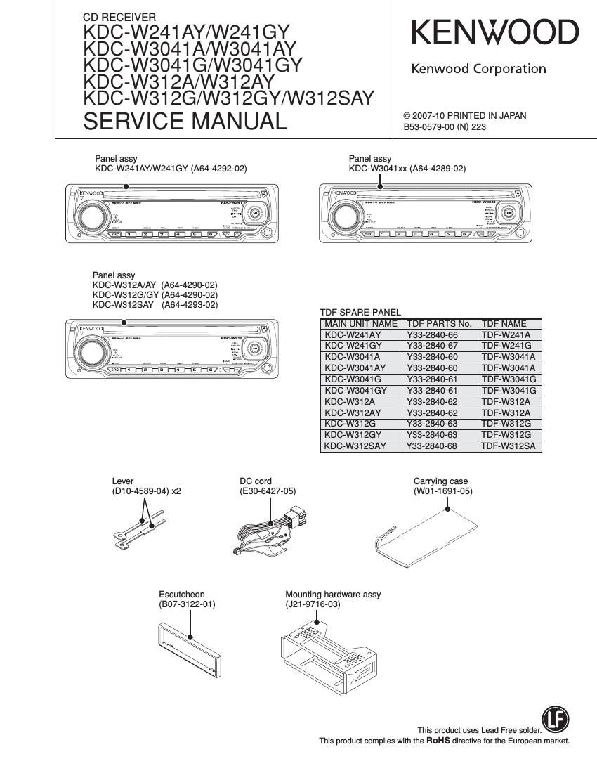
Kenwood KDCW 3041 A Service Manual

This is the 40 pages manual for Kenwood KDCW 3041 A Service Manual.
Read or download the pdf for free. If you want to contribute, please mail your pdfs to info@audioservicemanuals.com.

Page: 1 / 40
left right
Kenwood KDCW 3041 A Service Manual

Extracted text from Kenwood KDCW 3041 A Service Manual (Ocr-read)


Page 3

KDC-W241AY/W24iGY/W3041A/W3041AY/W3041G

/W3041GY/W312A/W312AY/W312G/W312GY/W312SAY

COMPONENTS DESCRIPTION

0 ELECTRIC UNIT (X34-565x-xx)

Ref. No. Application I Function Operation I Condition I Compatibility
|C1 System p-COM Controls FM/AM tuner, the changer, CD mechanism, panel, volume and tone.
IC2,3 E-VOL Controls the source, volume and tone.
|C4 Power Supply [0 Outputs 5Vx2, 8.1Vx2, 10.2V, P-CON and P-ANT.

ICS Power IC Amplifies the front L/R and the rear L/R to 50W maximum.

|C7 RDS IC RDS decoder.

108 Reset IC Lo when detection voltage goes below 3.6V.

02 Servo+B AVFl When 03's base goes Hi, Servo+B AVFi outputs 7.5V.

03 Control SW for Servo+B ON when the base goes Hi.

07 VFD+B SW ON when the base goes Hi.

08 VFD+B AVR When 09's base goes Hi, Servo+B AVFi outputs 10.5V.

09 Control SW for VFD+B ON when the base goes Hi.

011 14V SW ON when the base goes Hi.

012 14V SW ON when the base goes Lo.

0101 ACC DET ON when the base goes Hi during A00 is applied.

0102 Serge DET When the base goes Hi, surge voltage is detected.

0103 BU DET ON when the base goes Hi during BU is applied.

0104,105 Mute Control ON when the base goes Hi.

0301 Panel 5V SW ON when the base goes Lo.

0402 Quick Charge Voltage SW Charges voltage quickly when the base goes Hi.

0701 ,702 Pre-out Mute SW When a base of the 4 transistors goes Hi, pre-out is muted.

0705 Mute Driver for Pre-out ON when the base goes Lo.

0901 DC Offset DET ON when the base goes Hi after 0902's and 0903's outputs are separated.

0902,903 DC Offset DET SW ON when the bases go Lo after ICG's SP-OUTs (DC) are separated.
O SWITCH UNlT (X16-617x-xx)

Ref. No. Application I Function Operation I Condition I Compatibility
lC1 VFD Driver
IC3 Remote Control Sensor

0 CD PLAYER UNIT (X32-5970-02)

Ref. No. Application I Function Operation I Condition I Compatibility
IC3 4ch BTL Driver Egierréogr 2:12:21: & tracking coil, driver for sled & spindle motor, and operation for disc
|C4 Servo DSP with built-in Audio DAC With built-in MP3/WMA/AAC decoder and 1M-bit-SRAM.
|C5 D1.5V REG. Power supply for digital 1.5V.
ICS D3.3V REG. Power supply for digital 3.3V.
|C11 BU1.5V REG. Power supply for back-up1.5V.
01 AFC (Auto Power Control) Drives LD (Laser Diode).

Page 17

KDC-W241AY/W241GY/W3041A/W3041AY/W3041G
/W3041GY/W312A/W312AY/W312G/W312GY/W3128AY

ROM DATA TRANSFER PROCESSES

4. In case of applying a new ROM correction when front-end
(A1) is replaced (There is ROM correction data.)

5. In case of applying a new ROM correction even when
front-end (A1) is not replaced.

(D

Mother unit (X34-)

SYSTEM
FRONT- u-COM (lCt)

END(A1) I

E2PROM ROMcqmmmn
Tuner adjustment
Other

A

E2PROM circuit pattern

Install new E2PROM. (E2PROM that has been updated with
ROM correction)

(i)

Mother unit (X34-)

SYSTEM
FRONF wCOMUCfl
END(A1) I
E2PROM E2PROM

G

Turn power on.

Press and hold the [t] and [3] keys, press reset button. (Enter
the system in the test mode.)

Press [B.BOOST] key. (ROM data System enters data
transfer mode.)

Press [i441 (or [>>I] .) (Select WRT)

Press [NI] key for 1 second or longer. (Data transfer)

(3.)

Mother unit (X34-)

SYSTEM
FRONF woomucn
END(AU

EZPROM «II E2PROM


System prCOM (ICl) copies
the ROM correction data on the
mother unit (X347) into EZPROM
in the frontend (A1)

WRT 0
. .
V£:},lncaseoffi]

Press [>ii] key. (Exit ROM
data transfer mode.)

In case of [4]

Press (i441 (or [>>i] .) (Select READ)
Press [>ii] key for 1 second or longer. (Data transfer)

Mother unit (X34-)

SYSTEM
FRONF wcomacn
END(AU

E2PROM II. E2PROM


System ROOM (IC1) copies
data in the frontend (A1) inth the
E2PROM on the mother unit (X347).
(ROM correction and other data)

READ OK R-OK
> >

17