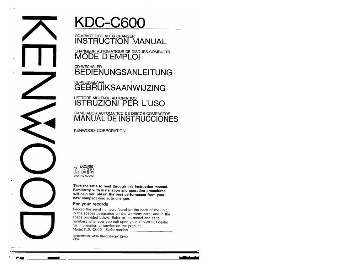
Kenwood KDCC 600 Owners Manual

This is the 19 pages manual for Kenwood KDCC 600 Owners Manual.
Read or download the pdf for free. If you want to contribute, please mail your pdfs to info@audioservicemanuals.com.

Page: 1 / 19
left right
Kenwood KDCC 600 Owners Manual

Extracted text from Kenwood KDCC 600 Owners Manual (Ocr-read)


Page 1

GOO/ANEDI

;

KDC-C6OO

COMPACT DISC AUTO CHANGER

INSTRUCTION MANUAL

CHANGEUFI AUTOMATIOUE DE DISQUES COMPACTS

MODE D EMPLOI

CD-WECHSLER

BEDIENUNGSANLEITUNG

CD- WESSELAAR

GEBRUIKSAANWIJZING

LETTORE MULTI-CD AUTOMATIOO

ISTRUZIONI PER L'USO

CAMBIADOR AUTOMATICO DE DISCOS COMPACTOS

MANUAL DE INSTRUCCIONES

KENWOOD CORPORATION

EUMPACT
DIGITAL AUDIO

Take the time to read through this instruction manual.
Familiarity with installation and operation procedures
will help you obtain the best performance from your
new compact disc auto changer.

For your records

Record the serial number, found on the back of the unit
in the spaces designated on the warranty card and in the
space provided below. Refer to the model and serial
numbers whenever you call upon your KENWOOD dealer
for Information or service on the product.

Model KDC-CBOO Serial number

@371le IN JAPAN swag-com. EJ(MC)
9 2

Page 2

WARNING

CAUTION
The use of optical instruments with this product will increase aye hazard.

INFORMATION

This equipment generates and uses radio frequency energy and if not installed and used
properly. that is, in strict accordance with the manufacturer's instructions, may cause
interference to radio and television reception. It has been type tested and found to
comply with the limits for a Class B computing device in accordance with the
specifications in Subpart J of Part l5 of FCC Rules, which are designed to provide
reasonable protection against such interference in a residential installation. However,
there is no guarantee that interference will not occur in a particular installation it this
equipment does cause interference to radio or television reception, which can be
determined by turning the equipment off and on, the user is encouraged to try to
correct the interference by one or more of the following measures:

Reorient the receiving antenna

Relocate this equipment with respect to the receiver

Move this equipment away from the receiver

Plug this equipment into a different outlet so that equment and receiver are on

different branch circuits.
If necessary, the user should consult the dealer or an experienced radio/televisicn
technician for additional suggestions. The user may find the following booklet prepared
by the Federal Communications Commission helpful:
"How to identify and Reso'va Radio-TV Interference Problems".
This booklet is available from the U.S. Government Printing Office, Washington, DC
20402, Stock No, 004-000-00345-4.

0 As the laser beam used in this compact disc player is harmful to the eyes, do not
attempt to d:sassemble the cabinet. Refer servicing to qualified personnel only.

FCC WARNING:

This equipment may generate or use radio frequency energy. Changes or modifications
to this equipment may cause harmful interference unless the modifications are expressly
approved in the instruction manual. The user could lose the authority to operate this
equipment if an unauthorized change or modification is made.

NOTE:

This equipment has been tested and found to comply with the limits for a Class B digital

device, pursuant to Part 15 of the FCC Rules. These limits are designed to provide

reasonable protection against harmful interference in a residential installation. This

eqUipment may cause harmful interference to radio communications, if it is not installed

and used in accordance with the instructions. However, there is no guarantee that

interference will not occur in a particular installation.. If this equipment does cause

harmful interference to radio or television reception, which can be determined by turning

the eqUipment off and on, the user is encouraged to try to correct the interference by

one or more of the following measures:

0 Reorient or relocate the receiving antenna.

I Increase the separation between the equipment and receiver.

I Connect the equipment into an outlet on a circuit defferent from that to which the
receiver is connected.

I Consult the dealer or an experienced radio/TV technician for help,

2

Page 14

r


INSTALLATION

Mounting Diagram 2

: Horizontal installation

1 Attach the brackets Q. to the main unll.


Attach the
brackets with

ths screws

inserted In the

blackened

holes. (Do the

same for the
left side also.)

(3 Bracket @ Washer assembly screw
(M 5 X l2l

Drill holas appmximmelv 4 mm in dlameter in the installation surface, align the bracket (i)
holes with the drilled holes and secure the unit in position.

© Tapping screw l¢5x 20}

M

Ill