Kenwood KDCC 510 FM Service Manual

This is the 15 pages manual for Kenwood KDCC 510 FM Service Manual.
Read or download the pdf for free. If you want to contribute, please mail your pdfs to info@audioservicemanuals.com.

Page: 1 / 15
left right
Kenwood KDCC 510 FM Service Manual

Extracted text from Kenwood KDCC 510 FM Service Manual (Ocr-read)


Page 1

bk,

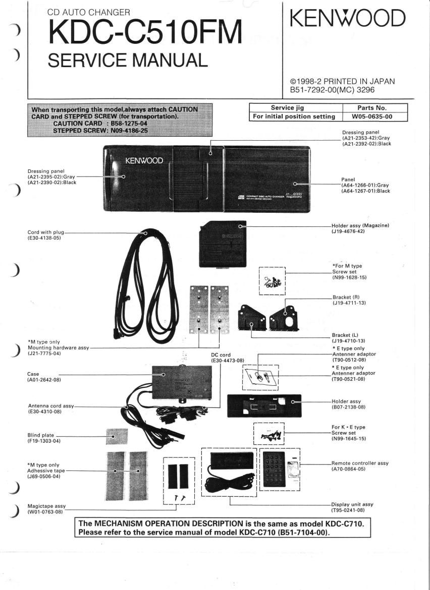
CDKBCEADNG-ERCSWFM KENWOOD

SERVICE MANUAL

©1998-2 PRINTED IN JAPAN
B51-7292-OO(MC) 3296

Service jig Parts No.

For initial position setting W05-0635-00

Dressing panel
(A21-23537A2):Gray
lAZ1-2392-02):B|ack

KENWOOD

Dressing panel 3
(A21-2395-02l:Gray -¢
(A2172390702):B|ack

Panel

(A64A1266-01):Gray
,,,,, lA64-1267-01):Black
24:me14"0 wms- «ad"

O---~-iHolder assy (Magazine)

Cord with plug-.-__- (J19-4676~42)
(E3074138705)
For M type
_}-Screw set
I (N99- 1628- 15)
l
l
Bracket (R)

(9471143)

5

Brackel (Ll


M lype only (J19-4710~13)
Mounting hardware assy * E type only
217777543 DC cord Anrenner adaptor
(Elm-447303) USO-0512708)
* E type only
Case _-.-. Antenner adaptor
(A01-2642-OB) (T90»0521-08l
Holder assy
Antenna cord assy_._». (BO772138»08)
(E30-43IO-08)
:- ;or K- E type
I lf---- crew set
BlInd plate -.
(HS-130304) L__ (N99- 1645- 15)
rfi F
__-__fi ' | I
*M lype only :- | I H IC'U-_Remote controller assy
Adhessive lapea-o-o I i I I I .I IA7oroas4-05)
(JESS-0506704) l l | I l I
l | l "I
I I I I |_ ______ _l
L r r J L---I---~J
Magictaoe assvg-w-J- Display unit assy
(W01 0763 08) (T95-0241-08l

The MECHANISM OPERATION DESCRIPTION is the same as model KDC-C710.
Please refer to the service manual of model KDC-C710 (351-7104-00l.

Page 2

wk)

Vb

KDC-C51 OFM
MICROCOMPUTER'S DESCRIPTION

TEST Modes
E-88 test mode

oHow to enter
While holding the magazine eject SW, reset the unit and keep on holding the eject SW for more second to
enter the E-88 mode.
(Note) In the E-88 mode, the initial position detection operation at the time of reset start is not performed.

OManual operation functions
The E-88 display appears when the H/U is set to the changer mode.
In this condition, the changer mechanism can be operated manually using the track search up/down and disc
search up/down keys.

Track search Up key: Operates the spindle/loading motor in the direction for pulling the disc tray into

the mechanism deck (disc loading direction).

Track search Down key: Operates the spindle/loading motor in the direction for returning the disc tray into

the magazine (disc ejection direction).

Disc search Up key: Operates the ELV motor in the direction for moving the mechanism deck upward.
Disc search Down key: Operates the ELV motor in the direction for moving the mechanism deck
downward.

oPosition adjustment function
This function writes the mechanism position adjustment values in the EEPROM in the E88 mode.

Adjustment procedure

1.

2.

With the mechanism in the magazine ejection condition, move the mechanism manually up and down to set
the mechanism to the reference position.

Pressing the REP key of the H/U starts the judgment of the mechanism position and the distinction whether
the changer is a 6~disc or 10»disc changer.

If the mechanism position is extremely deviated from the reference position, the processing is aborted
immediately.

. The offset from the reference position is calculated and the 6/10 data and offset values are written in the

EEPROM.

. Data is read from the EEPROM to judge whether it has been written normally.

When it is judged that the write operation has completed normally, the mechanism deck moves to the
magazine ejection standby position.
When it is judged that the write operation was abnormal, the mechanism performs no operation.

(Note) Mechanism reference position

6-disc mechanism: Position of the 3rd stage
10-disc mechanism: Position of the em stage