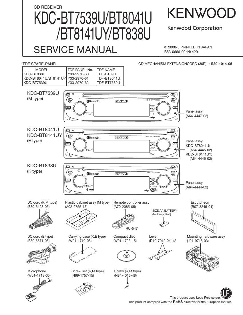
Kenwood KDCBT 8141 U Service Manual

This is the 52 pages manual for Kenwood KDCBT 8141 U Service Manual.
Read or download the pdf for free. If you want to contribute, please mail your pdfs to info@audioservicemanuals.com.

Page: 1 / 52
left right
Kenwood KDCBT 8141 U Service Manual

Extracted text from Kenwood KDCBT 8141 U Service Manual (Ocr-read)


Page 9

KDC-BT7539U/BT804I U

/ BT81 4] UY/ BT838U

MICROCOMPUTERS TERMINAL DESCRIPTION

Pin No. Pin Name l/O Application vaIIIeIItI-IlIle Processing Operation Description
79 LX7REQiM 0 Communication request to slave unit
79 NC 0 Not used (Models not-supporting LX-BUS) Output is fixed to L
80 LX7MUTE | Mute request from slave unit H: Mute ON, L: Mute OFF
80 NC 0 Not used (Models not-supporting LX-BUS) Output is fixed to L
81 LX,CON O Start-up request to slave unit H: Slave unit ON, L: Slave unit OFF
81 NC 0 Not used (Models not-supporting LX-BUS) Output is fixed to L
82 LX7RST O Hardware-reset to slave unit H: Reset, L: Normal
82 NC 0 Not used (Models not-supporting LX-BUS) Output is fixed to L
83 MUTEiPREiFR 0 External PREOUTiMUTE F/R Obit, L during momentary power down
84 MUTE PRE SW 0 External PREOUTiMUTE SUB Obit, L during momentary power down
MUTE72 shock noise measure Use in addition to MUTE72:
85 PONiAM I/O AM+B power supply control terminal H: ON when receiving AM, Hi-Z: OFF in other cases
86 TUN,|FC,OUT | F/E lFC OUT Input terminal H: Station found, L: Station not found
87 TUN,SMETER | 8 meter voltage detection terminal
88 RDS,NOISE | FM noise voltage detection terminal
88 NC 0 Not used (Models without RDS) Output is fixed to L
89 RDS,AFS,M I/O Time constant switching when noise IS L: During AF search, Hi-Z: In normal condition
detected
89 NC 0 Not used (Models without RDS) Output is fixed to L
90 TYPEJ | ND 5 patterns (1) Refer to Destination table
90 NC 0 Not used (Models without USB) Output is fixed to L
91 TYPE72 | ND 5 patterns (1) Refer to Destination table"
91 NC 0 Not used (Models without USB) Output is fixed to L
9293 NC 0 Not used Output is fixed to L
94 AVSS -
95 NC 0 Not used Output is fixed to L
96 VREF -
97 AVCC -
98 LX7DATA78 | Data from slave unit
98 NC 0 Not used (Models not-supporting LX-BUS) Output is fixed to L
99 LXiDATAiM 0 Data to slave unit
99 NC 0 Not used (Models not-supporting LX-BUS) Output is fixed to L
100 LX,CLK I/O LX BUS clock
100 NC 0 Not used (Models not-supporting LX-BUS) Output is fixed to L
Truth value table
5) Destination setting
Type1 (90) Type2 (91)
Model name TIE: Ty9p1e2 Pull up Pull down Pull up Pull down Features
R645 R644 R643 R642
KDC-BT838U 1 1 x 22k >< 22k BT BLUE
KDC-BT8041 U 1 5 x 22k 22k x BT BLUE
KDC-BT8141UY 1 4 x 22k 22k 47k BT BLUE
KDC-BT7539U 1 2 x 22k 47k 22k BT BLUE

Page 15

KDC-BT7539U/BT804I U

/BT8141UY/BT838U

TEST MODE

b. Press and hold [HI] key for 2 seconds to make the cur-
rent receive level to be the seek stop level in order to
start writing the adjustment values in E2PROM. At the
successful completion of the writing, EP7WRITE is
displayed. (In this step, use Local Seek ON/OFF setup
to change the destination of the writing.)

Seek Stop Level Adjustment (Manual)

(Display) MleIKeTe-8v \l : When at Normal (Local OFF)
(Display) MNLyL.44\L I : When at Local (Local ON)

\Adjustment values
Contents written in E2PROM as
the initial values are displayed.

a. In the band in which Local Seek ON/OFF is selectable,
Press [AUTO] / [Tl] key briefly to change between Lo-
cal Seek ON and OFF.

b. Use [K4] / [>>|] key (which can be pressed and con-
tinuously held) to manually adjust the seek stop level
between 0.00 and 4.49V (K/M), and between 0.00 and
4.70V (E), depending on the destination.

* The key keeps functioning downwards after the level
becomes 0.00V but in the meantime the level will be-
come 0.00V as it is displayed.

c. Press and hold [>ll] key for 2 seconds to make the volt-
age that is adjusted in the above step to be the seek
stop level and to start writing the voltage in E2PROM.
At the successful completion of the writing, EP,
WRITE is displayed. (In this step, use Local Seek ON/
OFF setup to change the destination of the writing.)

. Press [>ll] key briefly to exit from TUNER Adjustment
mode (and to keep running the Test mode).

0 RDS automatic measurement (European model)

Add the process to replace the visual inspection of PS
display previously done in the production line.

When it is confirmed that the PS data has been received
and that the content of the P8 is RDsiTEST, force to
OFF the P-CON terminal. (The symbol, 7" indicates the
blank. )

a Make this as the process dedicated for the test mode.

P-CON is recovered by Power OFFeON.

0 Special display in tuner sourse

Error is found in front-end, etc. if indications below are
displayed while in tuner sourse.

0 TNE2P7NG ...... E2PROM (inside front-end) values are
still default (not determined)

0 TNCONiNG ...... Cannot communicate with the front-
end.

. K3| forced switching

Every time when [6] key is pressed in tuner FM band,
switched in the following order: AUTOaForced WIDE
aForced MIDDLEaForced NARROWaAUTO. Default
status is AUTO, and displayed as shown below.

0 AUTO aF1 98.1
0 Forced WIDE wF1 98.1
- Forced MIDDLE mF1 98.1

0 Forced NARROW... nF1 98.1

0 CD source test mode specification

Jumps to the following tracks by pressing the [>ll] key.
9e15610e11a12e13622e14a9 (recursive)

Note that when playing a CD-DA disc and MP3 / WMA
/AAC / WAV discs with 8 files or less, the disc is played
from the 1 track in the normal order.

Pressing the [ll<] key goes back by 1 track from the track
being played.

While in CD source, press the [1] key ([1] and [FM] keys
are for CD-DA) briefly to jump to No.28.

While in CD source, press the [2] key briefly to jump to
No.14.

While in CD source, press the [3] key briefly to display
CD mechanism model name and the version.

Press the [3] key briefly again to return to the normal dis-
play. (Time code display)

6E20 V0123
SERV V1.23
BOOT V1.23

While in CD source, press the [6] key ([6] and [AM] keys

are for CD-DA) briefly to jump to No.15. At this time, the

volume value is set to 27 (2V PRE).

(*1) Only in the test mode, [1] key, [2] key, [3] key and [6]
key shall be displayed on the multi-function key.

1. Press the [FNC] key briefly to make the multi»
function display.

2. Rotate the control knob on the right side and use
the [l<<] / [>>l] keys to display the target key in the
center.

3. Press the [>ll] key briefly to finalize the display.

(*2) Perform the same operations as above on the keys,

[1], [2], [3], and [6] on the remote controller.

0 AUDIO adjust mode

Press the [AUD] key briefly to enter the audio adjustment
mode.

15

Page 18

KDC-BT7539U/BT804I U
/BT8I4I UY/BT838U

18

TEST MODE

[yyfl Key pressed briefly: AUDIO data initialization [4] Key pressed briefly: CD operation time is displayed.
key (Display) AUDJNIT [AM] key (Display) CDTimionxi (00~50 is displayed for xx.
[K4] Key pressed briefly: Forced Power OFF data displayed. key (Emma When less than 1 hour,
key Press and hold: To clear the forced power OFF infor- "" display by increment 0f 10
mation. (Press and hold for 2 seconds while the forced T minutes.)
power OFF data is displayed.) xxxxx (00001-10922 is displayed
(Display) POFF, - - - (No Forced Power OFF) for XXXXXX'VJ
SEC (Forced Power OFF because of I, MAX 10922 (hours)
missing Security Code) [5] Key pressed briefly: Number of CD EJECT times is
PNL (Forced Power OFF because of [FM] key displayed.
system u-com and panel commu- key (Remote (Display) EjeCanxxxx MAX 65535 (times)
nication error) UIKIIUIIUI)
[AUD] Key pressed briefly: iPod authentication IC installation [>II] key Key pressed briefly: Invalid
key status display Press and hold: To clear the service information that
(Display) iPod, OK, (Installation status OK) is being displayed. (Press and hold for 2 seconds
NG (Installation status NG) while each service information is displayed.)
[FNC] Key pressed briefly; Multi-function display [FNC] key Key pressed briefly: Version & Service information
key Press and hold: Version & Service information display display mode OFF
mode ON
Refer to the Table 1' Table 2 - CD information display mode
[11:53] :eoydgrgshsed briefly. Version 8 Sewlce information display EC communication condition and CD mechanism error log
lsp ay
Sixteen Refer to the Table 1. (Display) [20700
(Display) ERRJ-AA, 2-A, 3-AA
[NI] Key pressed briefly: CD information display mode ON * OK or Neil is displayed for Moore / ll_li or the error
key Refer to the Table 2 code is displayed for A/A".
[AM] CD loading error log display
Table 1 - Version & Service information display mode key (Display) LoadiErrori
[1] Key pressed briefly: Version is displayed (Switching) (Display) 7(1) XX (2) XX
key (Display) 00715WK78YS123 T (Number of times is displayed for xx.) MAX 99 (times)
(Remote (Display) STYPE: xfoAN1I11 CD ejection error log display
controller] (Display) PTYPE: xi (Display) EjectiErrori
4:1 STYPE indicates system p-com destination, and (Display) 7(1) XX, (2) XX
PTYPE indicates panel p-com destination, and (Display) 7(3) XX, (4) XX
show real-time condition of the destination termi- (Number Of times is displayed for XXU MAX 99 (times)
[AM] nal l CD time code error count data display (missing counts)
key M Use the remote controller [1] key or the [|<<] / (Display) CountiLose
[FM] keys to switch. [FM] (Display) ,CDDAi: xx
T (Display) BT7VER : HWXXX78WXXX key (Display) iCDROM: XX
(BT module H/W & S/W VEYSiOFi) (Number of times is displayed for xx.) MAX 99 (times)
(Display) ADDR I XXXXXXXXXXXX CD time code error count data display (count not updated)
. (BT module Address) (Display) Countistay
(Display) PIN : xxxxxxxx (Display) ,CDDAi: xx
(BT module PIN Code) (Display) ,CDROM: xx
[2] Key pressed briefly: Serial No. is displayed (8 digitS) (Number of limes is displayed for xxJ MAX 99 (times)
1 (R1236 (Display) SNOJXXXXXXX [>ll] Key pressed briefly: CD information display mode OFF
key Press and hold: To clear entire CD information (Press and
[FM] mmmuen hold for 2 seconds)
key [3] Key pressed briefly: Power ON time is displayed.

key

(Remote

(Display) PonTimionx, (00~50 is displayed for xx".
When less than 1 hour,
display by increment of 10
minutes.)
xxxxx (00001-10922 is displayed
for xxxxxx.)

controller)

MAX 10922 (hours)

O Initializing AUDIO-related setting value
Press the [>Il] key briefly in the STANDBY source to reset
the AUDIO setting value to the test mode default value.

Page 20

KDC-BT7539U/BT8041 U
/BT8141UY/BT838U

20

TEST MODE

[Service Information]

0 Displays power ON time is displayed.
0 Displays CD operation time.

0 Displays number of CD EJECT times.
0 Displays forced Power OFF data.
[DC offset error detection information]

0 DC offset error detection display 1

0 DC offset error detection display 2
[BT memory information]

- Pairing information

- Preset telephone number information
- Friendly name (Setup)

0 PIN code

. After the initialization process is completed, the following

is displayed.
When successfully completed

E2P,CLR:O
BTgCLR :O

When finished but unsuccessful 1: Initialization of BT
memory information is NG

E2P,CLR:O
BTgCLR :><

When finished but unsuccessful 2: Initialization of
E2PROM in TUNER PACK is NG

E2P,CLR:><
BTiCLR :O

When finished but unsuccessful 3: Initialization NG

E2P,CLR: ><
BT,CLR :><
(Note)

it takes about 10 seconds to initialize BT memory infor-
mation and during this initialization process the following
-" is shown that indicates the Not-yet»decided" status.

E2P,CLR:O
BTicLR :-

. in this mode, even if the specified time has passed, the

backup memory items are not written into E2PROM.

4. This mode is cancelled by resetting. (The last screen will

not be retained.)

(Note) in this mode, the DC error detection display, Pro-
tect" is not shown.

Do not touch any key in this mode (while in clearing).
Never turn ON or OFF in this mode.

0 Clearing DC offset error detection information
(Clearing E2PROM data within the front end)

1. Press and hold [A'l'l] and [AUD] keys and reset-start to
go into the DC offset error display mode.
(While ----" is being displayed, power can be ON for 30
minutes.)

2. While in STANDBY source, the current DC offset error
detection condition is displayed.

DC offset error detection display 1 (To show such detec-
tion as the improper connection, and other detection)
(Display) DC1 70K, (not detected)
ERR (Improper connection or other error
is detected.)

Upper
row

DC offset error detection display 2 (To show the number
of capacitor leaks.)
(Display) ocz,oi (not detected)

1 (Leak is detected once.)

2 (Leak is detected twice.)

3 (Leak is detected 3 times.)

4 (Leak is detected 4 times or more.)

Middle
row

3. While the DC offset error detection condition is being
displayed as above, press and hold [1] key for 2 seconds
to clear the information about the improper connection,
and other detection. Press and hold [2] key for 2 seconds
to clear the information about the number of capacitor
leaks. (Clear E2PROM)

4. DC offset error display mode is cancelled by resetting.
(The last screen will not be retained.)

(Note) in this mode, the DC offset error detection display,
Protect is not shown.

0 FM/AM channel space switching (Models for
destination K and M")
FM: 50kHz<->200kHz, AM: 9kHz<->10kHz

0 While power is OFF, press and hold [FNC] and [AUTO]/fl'l]
keys, and press [SRC] key to power ON.

0 Security
How to enter the forced POWER ON mode
While 7 7 7 7" is being displayed, while simultaneously

pressing [FNC] key and [NI] key, press [RESET] button,
With this, it is possible to turn the power on for 30 min-
utes only.

- How to register the security code on the Car
Audio Passport sheet after replacing E2PROM
(inside the front-end) (code security models)

1. Enter the test mode. (Refer to How to enter the test
mode")