Kenwood KDC 5010 Service Manual

This is the 36 pages manual for Kenwood KDC 5010 Service Manual.
Read or download the pdf for free. If you want to contribute, please mail your pdfs to info@audioservicemanuals.com.

Page: 1 / 36
left right
Kenwood KDC 5010 Service Manual

Extracted text from Kenwood KDC 5010 Service Manual (Ocr-read)


Page 2

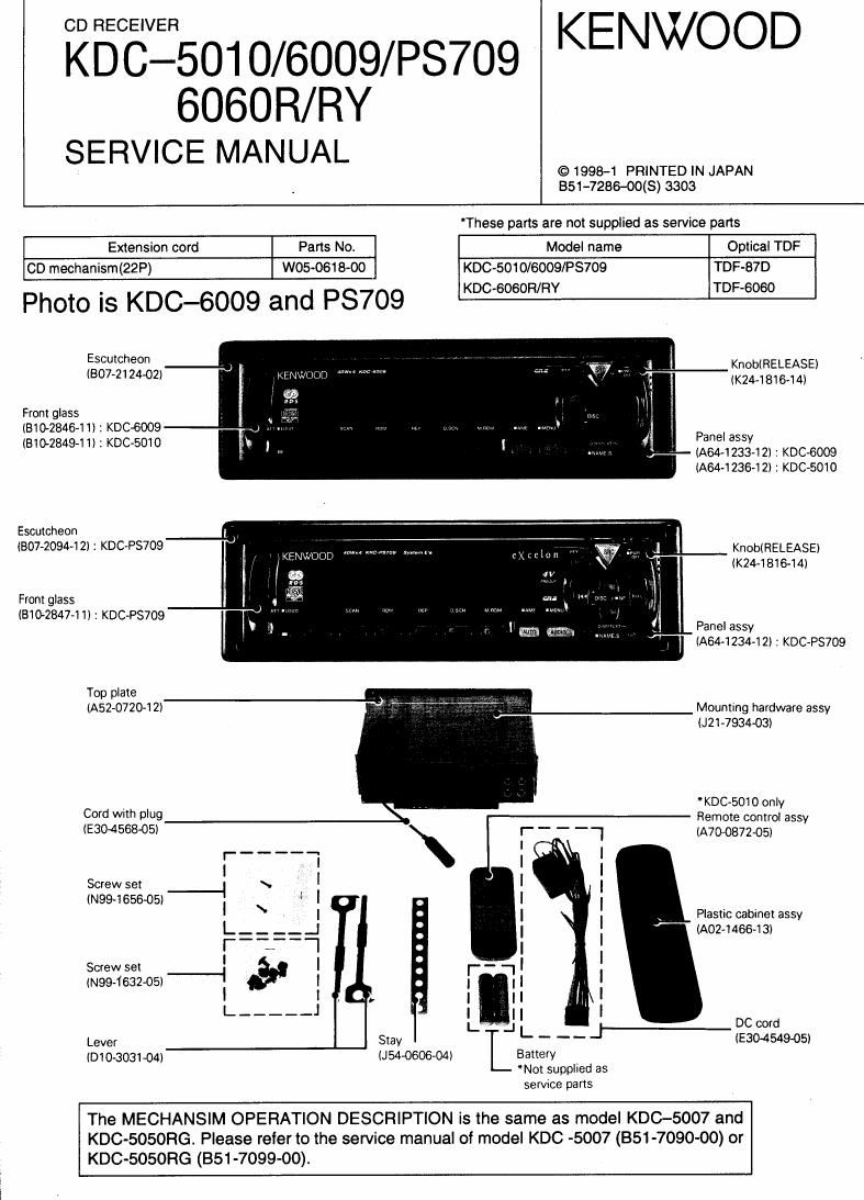
f KDC-5010/6009/PS709/6060R/RY

Photo is KDC-6060R

Front glass
(5102851411)

Escutcheon
(307412402) KnobI RELEASE)
(K244816441!
Panel assy
(AM-12384 2!
Top plate .
(A52-0720-12) figh- Mounting hardware assy
021393403)
DC cord
(E30455805)

Cord with pIug
(EEO-456805)

Sems
(NW-1885405)
PIastxc cabinet assy
(Am-14664 3)
I {I
Lever
(010303104) L!
T
Antenna adaptor
(T90051205I
BLOCK DIAGRAM ...................... EXPLODED VIEW (MECHANISM) .,


EXPLODED VIEW (UNIT) I
PARTS LIST ............
SPECIFICATIONS ..

COMPONENTS DESCRIPTION
MICROCOMPUTER'S DESCRIPTION
TEST MODE AND ADJUSTMENT
PC BOARD .....................
SCHEMATIC DIAGRAM .

Page 6

KDC-501 0/6009/ P8709/6060R/ RY

OTerminal description

MICROCOMPUTERS DESCRIPTION

System [.1 -Com : UPD784214GF(X25-8010-XX : IC1)

Pin No. Pin Name I/O Function Description Processing Operation
1 P60/A16 l TYPEO Destination type terminal 0
2 P61/A17 l TYPE1 Destination type terminal 1
3 P62/A18 | TYPE2 Destination type terminal 2
4 P63/A19 O CH RST Changer reset output Active : H
5 P64/RD 0 NC (Not used)
6 PBS/WP 0 NC (Not used)
7 Pea/WAIT 0 NC (Not used)
8 P67/ASTB 0 NC (Not used)
9 Vdd - Positive power supply terminal
10 P1 OO/T l5/T 05 O P STBY Power lC standby terminal Power ON : H
11 P1 01/T |6/T 06 O SVR Power IC reset terminal Power ON 1 L
12 P102/Tl7/T07 0 NC (Not used)
13 P1 03/T l8/T 08 O P MUTE Power IC muting terminal Act'we : H
14 P30/TOO O ANT CON Antenna control terminal Active : H
15 P31/T01 0 NC (Not used)
16 P32/T 02 l DIMMER Small lamp detection terminal Active : L
17 P33/Tl1 O P CON Power control terminal Active: H
18 P34/T12 | ACC DET Acc detection terminal ACC OFF : H
19 P35/TIOO | REMO Remote control input terminal
20 P36/Tl01 0 P ON u-com peripheral power terminal Active : H
21 P37 | BU DET Momentary power down detection terminal Momentary power down : H
22 TEST - TEST Test terminal
23 P90 l/O IC2 SDA ICZ, IC5, EEPROM data line
24 P91 0 |C2 SCK I02, ICS, EEPROM clock line
25 P92 0 MUTE Muting terminal Active : H
26 P93 0 SW5 5V power supply terminal Active : L
27 P94 0 NC (Not used)
28 P95 0 CHCON2 Changer 2 control terminal Active : L
29 P120/RTPO O CHCON1 Changer 1 control terminal Active : H
30 P121/RTP1 | CH MUTE Changer muting input terminal Muting Requested : H
31 P122/RTP2 O REQH Handshake request to changers Active : L
32 P123/RTP3 O lLL ON illumination output terminal Active : H
33 P124/RTP4 O DSI DSI output terminal Active : H
34 P125/RTP5 | CD SW2 12cm disc detection switch terminal ON : L
35 P126/RTP6 | CD SW1 Loading switch detection terminal ON : L
36 P127/RTP7 | M DATAM Data line from CD mechanism
37 Vdd - Positive power supply terminal
38 X2 - Main clock connection terminal
39 X1 - Main clock connection terminal
40 V55 - GND
41 XT2 - Sub clock connection terminal
42 XT1 - Sub clock connection terminal
43 RESET I Reset input terminal Active : L
44 POO/INTPO 0 NC Reset output to changers Active : H
45 P01/INTP1 I R CLK RDS clock input terminal
46 PO2/INTP2/NMI I REQC Handshake request from'changrs Active : L
47 POS/INTPS I EJECT Eject switch Active : L
48 P04/INTP4 O M CLK Clock line to CD mechanism
49 P05/INTP5 O M DATAS Data line to CD mechanism
50 P06/INTP6 l M SRQ Handshake request from CD mechanism Requested : t

Page 9

KDC-501 0/6009/PS709/6060R/RY
TEST MODE AND ADJUSTMENT

0TEST MODE AND ADJUSTMENT

1.

To enter test mode

While holding the key and preset IE] key, reset
the unit.

All indication segments are ON at the beginning of
test mode.

To release test mode
Simply reset the unit.
(NOTE):
The test mode is not canceled by ACO OFF,
power OFF, momentary power down or the
panel detaching.

FM signal meter voltage adjustment

1) Enter test mode.

2) Receive 98.1 MHz with the SG and set the ANT
input level to 35dBp. The modulation should be
off during this.

3) While holding preset key, press and hold
preset E! key for a few seconds.

4) ADJ OK" is displayed if the adjustment is OK
and "ADJ NG" is displayed if it is not good.

. AM SD voltage writing

1) Enter test mode.

2) Receive 999kHz or 1000kHz with the SG and
set the ANT input level to 35dBp.
The modulation should be oh during this.

3) While holding preset key, press and hold
preset [El key for a few seconds to write the SD
voltage.

5. CD receiver test mode specification

Pressing the El key jumps between tracks in the
following order.
No.9 -> No.15 -> No.10 -> No.11 -> No.12
-> No.13 -> No.14 -> No.19 (Same as the
biginning)
Pressing the E key jumps to the previous track
to the track being played.

. Audio adjustments

0 The volume is set to -10dB (which is shown as
30).

- The BASS/TREBLE and BALANCE/FADER
controls can be set to the full boost/full cut and full
front/full rear respectivily by pressing the /
keys.

- The high pass filter can be set to 220Hz/through
by pressing the / keys.

0 Note that, however, the non-fader control is varied
in +1dB/ ~1dB steps by pressing the / keys.