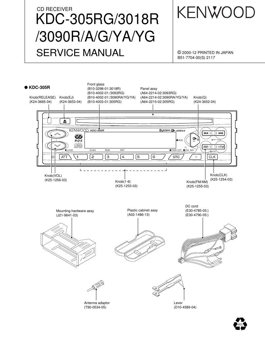
Kenwood KDC 305 RG Service Manual

This is the 18 pages manual for Kenwood KDC 305 RG Service Manual.
Read or download the pdf for free. If you want to contribute, please mail your pdfs to info@audioservicemanuals.com.

Page: 1 / 18
left right
Kenwood KDC 305 RG Service Manual

Extracted text from Kenwood KDC 305 RG Service Manual (Ocr-read)


Page 4

KDC-305RG/3018R/3090R/A/G/YA/YG

MICROCOMPUTER'S TERMINAL DESCRIPTION

OTerminal Description

Pin Function I/O Description Processing Operation
1 AV CONT 0 A/D converter reference voltage control output Hi: ON / Lo: OFF
2 |C2 TYPEO I |C2 setting terminal Lo: Initial value
3 |C2 TYPE I |C2 setting terminal "Lo: Initial value
4 AVSS - Ground connection terminal connected to GND
5 M MUTEL l Muting request from the MICOM. of CD mecha. "Lo": Mute request
6 NC 0 Not used
7 AVREF1 l D/A converter reference voltage input
8 ILLUMI O Illumination AVR ON/OFF control output Hi: AVR ON
9 L RES 0 Reset output to the LCD driver IC "Lo: Reset
10 PANEL l Panel open/close detection input "Lo: Panel closed
11 L DATAL I Data input from the LCD driver IC
12 L DATA8 0 Data output to the LCD driver IC
13 L CLK O Clock output to the LCD driver IC
14 NC 0 Not used
15 NC 0 Not used
16 CH-DATAC | Data input from changers
17 CH-DATAH 0 Data output to changers
18 CH-CLK l/O Clock input/output with changers
19 L CE 0 CE output to the LCD driver lC Hi: Active
20 NC 0 Not used
21 M RST 0 Reset output to the MICOM. of CD mecha. Lo: Reset
22 M STOP 0 Stop request to the MICOM. of CD mecha. Lo: Stop
23 MOSW 0 CD mechanism loading motor control output "Hi: Loading & Eject / "Lo: other
24 PLL SOL O Clock output to the tuner pack
25 AM+B O AM+B control Hi: during AM reception
26 FM+B O FM+B control Hi": during FM reception
27 M-SCL l/O Clock input/output with the MICOM. of CD mechat
28 DSI O DSI output Hi: LED ON
29 LO/EJ l/O CD mecha.Loading/Eject switching output "Lo": Loading / Hi": Eject
30 SW3 | Down & limit switch detection input "Hi": Chucking/"Lo": Pickup most inner position
31 R DATA | Data inputfrom RDS decoder
32 Ft QUAL I Quality input from RDS decoder
33 VSS1 - Ground connection terminal connected to GND
34 SD | SD input from the tuner pack Hi: Station detected
35 |C2 SCL O Clock output to the E-VOL. IC
36 M»SDA l/O Data input/output with the MICOM. of CD mecha.
37 PLL SDA l/O Data input/output with the tuner pack
38 |C2 SDA l/O Data input/output with the E-VOL. IC
39 MUTE O Mute control output Hi: Mute ON / "Lo: Mute OFF
40 NC 0 Not used
41 AFC 0 AFC control output Lo": during FM seek
42 CH-REQH 0 Request output to changers "L0": Request
43 CH-CON O Changer control "Lo": Standby / Hi": ON
44 NC 0 Not used
45 P MUTE 0 Power IC mute control Lo": Mute
46 SVR 0 Power IC reset terminal When the momentary power down, after ACC
OFF/ON is detected and after POWER ON/
OFF, the output goes Hi" temporarily.
47 STBY 0 Power IC standby control output "Hi": POWER ON mode
48 P CON 0 Power control "Hi: POWER ON mode except ALL OFF mode
49 P ANT 0 Antenna control Hi: during FM/AM reception
50 BEEP O BEEP sound output
51 ACC DET | ACC detection input Hi: ACC OFF / "Lo: ACC ON
52 BU DET | Momentary power down detection input Hi: When momentary power down detected
or BU OFF / "Lo: BU ON
53 NC 0 Not used