Kenwood KDC 3024 YG Service Manual

This is the 30 pages manual for Kenwood KDC 3024 YG Service Manual.
Read or download the pdf for free. If you want to contribute, please mail your pdfs to info@audioservicemanuals.com.

Page: 1 / 30
left right
Kenwood KDC 3024 YG Service Manual

Extracted text from Kenwood KDC 3024 YG Service Manual (Ocr-read)


Page 1

iERficgE53024A/G/YA/YG KENWOOD
KDC-307A/G/YA/YG

SERVICE MAN UAL ©2002-11 PRINTED IN JAPAN

353-0002-00 (N) 1874

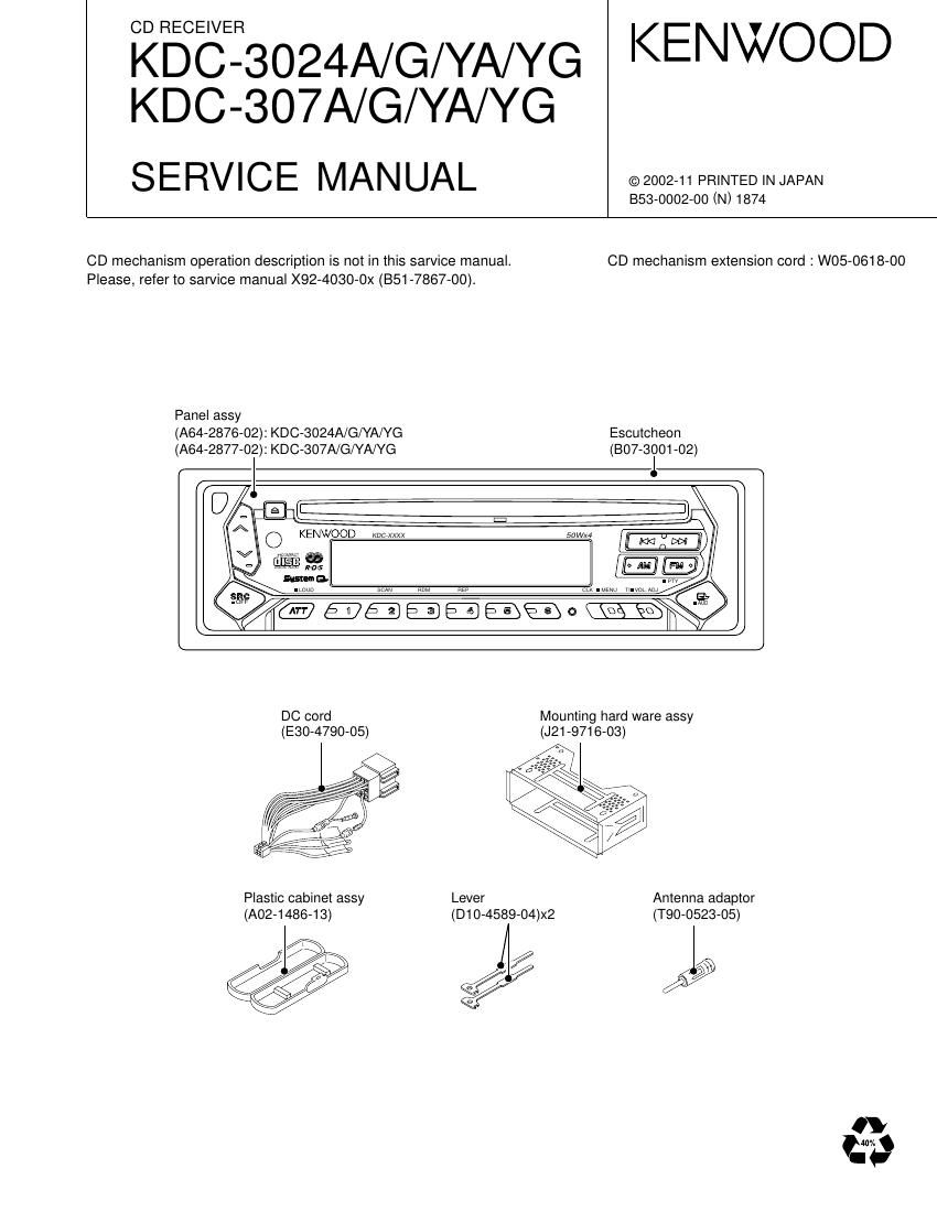
CD mechanism operation description is not in this sarvice manual. CD mechanism extension cord : W05-0618-00
Please, refer to sarvice manual X92-4030-0X (851-7867-00).

Panel assy
(A64-2876-02): KDC-3024A/G/YA/YG Escutcheon
(A64-2877-02): KDC-307A/G/YA/YG (807-3001-02)

KENWOOD we xxxx

DC cord Mounting hard ware assy
(E30-4790-05) (J21-9716-03)

Plastic cabinet assy Lever Antenna adaptor

(A02-1486-13) (D1 O-4589-04)><2 (T90-0523-05)

////; y/§§\ / 2/2 / Q

Page 5

KDC-3024A/G/YA/YG,307A/G/YA/YG
M icnocom PUTER'S TERMINAL DESCRIPTION

Pin No. Name I/O Description Processing Operation
43 B.U-DET | Back up detection terminal Hzpower down L:B.U. on
44 ACC-DET | ACC detection terminal HzACC OFF LzACC ON
45 PS1 _0 O POW?" SUPPIY '0 SW1 contra 0 BA4911 SW1 Power supply IC output
Audio 8V,P-CON PS1-2 PS1-1 PS1-0 Aev l P-CON l P-ANT
46 PS1-1 0 Power supply lC SW1 control 1 II: L(|l-l) H11) ON 51'8ny OFF
Audio 8V,P-CON |_ H H ON ON OFF
47 PS1-2 0 Power supply IC SW1 control 2 P-ANT H H H ON ON ON
48 PSZ-O 0 Power suPply '0 SW2 control 0 BA4911 sw2 Power supply IC output
lLL,FM,AM P6271 P8270 ILLUMI l FM | AM
L L srémevl OFF
_ Power supply lC SW2 control 1 H) (H ON
49 P82 1 O lLL,FM,AM H H ON l OFF | ON
50 BEEP BEEP
HzLight on L:Light off
When panel attached,output L
51 DSI 0 DS' control When panel detachedjlashing at the panel (H/L)
FIX model is output L
52 NC 0 Not used (out put L)
53 NC 0 Not used (out put L)
54 LOE/LIM SW | CD mechanism down&limit detection H:Chucking detection L:Normal
55 MO SW 0 CD mechanism loading motor control output H:Loading,Eject,Break L:Play
56 LO/EJ l/O CD mechanism loading/Eject switching terminal HzEject L:Loading
57 M-STOP 0 Stop output to the CD mechanism HzPlay L:Stop
58 M-RST 0 Reset output to the CD mechanism H:Normal L:CD mechanism reset
59 M-MUTE l Mute input from the CD mechanism Hzmute off Lzmute on
60 RESET Reset input from the System microcomputer
61 REMO l Remote control input
62 R-CLK l RDS clock input Except RDS model : output L
H:Changer detection
63 CH-REQC | Request input from the changer (new 5L) L:Request
Except Changer model : output L
. . , . HzNo disc
64 L08 SW | CD mechanism loading 5 SWItch detected L:DISK |N(Loading Stan)
Key input detected HzKey no input
65 KEY-REQ I (1 1 pin L connected to the DATA L) LzKey input (edge key data reading start)
66 12EJE SW | 12cm disc detected L2120m disc
67 VssO
68 VDD1
69 X2 A3 MAIN X'tal oscillating circuit A3 4.19MHz X'tal connection
70 X1 A3 MAIN X'tal oscillating circuit A3 4.19MH2 X'tal connection
71 IC TEST
72 XT2 Not used OPEN
73 XT1
74 VDDO VDD Connected to VDD
A/D converter reference voltage control output,
75 AVREFO connection to the 80pin AVCONT
76 S-METER l S-meter input
77 NOISE l FM noise detection input A3
2.5V or greateerAVI MUTE
78 PHONE | 2way mute 1.0V or lesszTEL MUTE
Except phone mute model : output L
79 NC 0 Not used (out put L)
80 AVCONT 0 A/D converter standard voltage control output :éairltfigififwfifiqnégfir active

Page 7

KDC-3024A/G/YA/YG,307A/G/YA/YG
M ICROCOM PUTER'S TERMINAL DESCRIPTION

Pin No. Name I/O Description Processing Operation
52 X2 0 Main clock output terminal
53 DVSS2 - Ground lines for digital circuit
54 XSUBl | When external DAC,external clock input terminal
55 XSUB2 O
56 TEST1 | Test port 1 Normal operation is H fixed
57 TEST2 | Test port 2 Normal operation is H fixed
58 NC 0 Not used
59 VER/HOR 0 Put length or breadth switching motor terminal HzPut length LzPut breadth
6O DRVfiMUTE 0 Driver mute control terminal L:MUTE ON HzMUTE OFF
61 /MUTE7L 0 Audio Lch MUTE output L:MUTE
62 /MUTE7R 0 Audio Rch MUTE output L:MUTE
63 lRST | LSI reset input terminal H:Normal LzReset
64 OCD,CLK | When 0CD connected, clock input
65 /MSTOP | Standby detection terminal H:Normal L:Mecha stop
66 DATA l/O I2C bus data line (communication line with system computer) At that time serial writer connected
67 SBlO I When connected to serial writer,data input terminal
68 /CLK l/O IZC bus clock line (communication line with system computer) At that time serial writer connected
69 TX 0 Digital audio interface signal output
70 EOCNT 0 RF EQ switching terminal sz2 times Hzx1 times
71 XSEL | During the external DAC connection MCLK external input (Hzinput)
72 MCNT | CD mecha Loading/Eject control ON/OFF L:OFF (HOST control) Hzmechanism control
73 P-ON 0 Audio and servo origin power control terminal L:power on Hzpower off
74 MOTOR O Loading/Eject control switching terminal At that time LO/EJ is "H"
75 LO/EJ O Loading/Eject control terminal or output L When 72pin (P82) is "L",output L"
76 CD-RW O CD»RW control terminal H:CD-RW L:normal
77 LDCNT 0 LD control terminal Operation is same LDON as timing
78 DVDD3 - Power supply for digital circuit
79 FOD 0 Focus driver output (PWM output)
80 TRD 0 Tracking driver output (PWM output)

System mi-com Destination type list

TYPE2 l TYPE1 l TYPEO 3 MODEL NAME
L l L l L l KDC-2024SA/SYA, 2024SG/SYG
L l L l H «Dc-2022, 2022v,202MR
PD780058GC499 L i H i L iRY-3910D, RX-4910D
L 1 H 1 H moo-4023, 2023, 3023
L l L l H lKDc-122,12zs
uPD780058GC501 L 1 H 1 H :KDc-1023, 10233
H l L l H lKDc-222, 2228
L l L l L l KDC-3024G/YG, 307G/YG
L 1 H 1 H 1KDc-3023R
PD780058G6502 H l L l L l KDC-3024A/YA, 307A/YA
H 1 L 1 H i KDC-4024/Y/V/YV
uPD780058GC503 L l L l L l KDC-2094YA/YG
H: R135 1 R137 1 R139
L: R136 3 R138 3 R140