Kenwood KDC 3024 A Service Manual

This is the 30 pages manual for Kenwood KDC 3024 A Service Manual.
Read or download the pdf for free. If you want to contribute, please mail your pdfs to info@audioservicemanuals.com.

Page: 1 / 30
left right
Kenwood KDC 3024 A Service Manual

Extracted text from Kenwood KDC 3024 A Service Manual (Ocr-read)


Page 1

iERficgE53024A/G/YA/YG KENWOOD
KDC-307A/G/YA/YG

SERVICE MAN UAL ©2002-11 PRINTED IN JAPAN

353-0002-00 (N) 1874

CD mechanism operation description is not in this sarvice manual. CD mechanism extension cord : W05-0618-00
Please, refer to sarvice manual X92-4030-0X (851-7867-00).

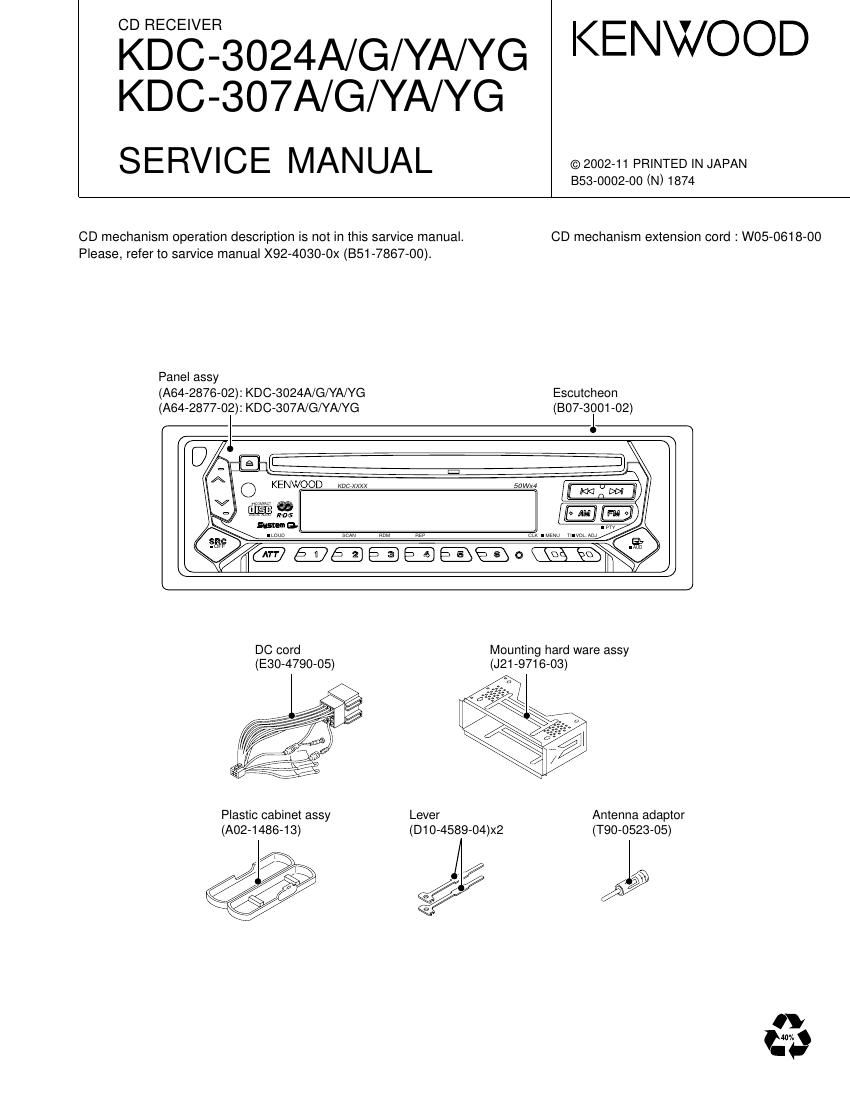
Panel assy
(A64-2876-02): KDC-3024A/G/YA/YG Escutcheon
(A64-2877-02): KDC-307A/G/YA/YG (807-3001-02)

KENWOOD we xxxx

DC cord Mounting hard ware assy
(E30-4790-05) (J21-9716-03)

Plastic cabinet assy Lever Antenna adaptor

(A02-1486-13) (D1 O-4589-04)><2 (T90-0523-05)

////; y/§§\ / 2/2 / Q

Page 4

KDC-3024A/G/YA/YG,307A/G/YA/YG
MICROCOM PUTER'S TERMINAL DESCRIPTION

0 SYSTEM MICROCOMPUTER uPD780058GC502 (X25 : IC1)

Pin No. Name l/O Description Processing Operation
1 TDF DET | Panel detection H:Panel detached L:Panel attached
H:Eject is completed
2 8EJE SW I Except 8cm CD modelzalways output L
3 NC 0 Not used (out put L)
4 Avss
HzPanel detached LzRESET
5 L-RST 0 LCD driver RESET A3 normal H , Power off L
When 7seg model,output L
. . H:Select (panel communication)
6 L-CE 0 LCD driver selection When panel attached,output L
7 AVREF1
8 NC Not used (connected to 9pin)
9 IC10-DATA I/O IC10,E2PROM data communication A3 non communication : H
10 IC10-CLK O IC10,E2PROM clock communication A3 non communication : H
Non communication : H
11 L-DATAL | Data input from the LCD driver When panel detached : L
A3 Pull down on X25 unit,Pull up on X16 unit
12 L-DATAS 0 Data output to the LCD driver When panel detached , output L
13 L-CLK O Clock output to the LCD driver When panel detached , output L
14 R-DATA | Data input from the RDS Except RDS model : output L
15 R-QUAL | Quality input from the RDS Except RDS model : output L
16 CH-DATAC | Data input from the changer (new 5L) Except changer model : output L
When non communication ,last data keeping
17 CH-DATAH 0 Data output to the changer (new 5L) Except changer model 2 output L
18 CH-CLK I/O Clock input/output with the Changer (new 5L) Ezgggtglfaflgearnmjondeevlvz output L
LzRequset
19 CH-REQH 0 Request output to the changer (new 5L) Except changer model : output L
20 NC 0 Not used (output L)
_ _ _ _ _ _ HzNormal LzFM/AM seek and AF search
21 AFS O N0ise detection time constant SWItching terminal A3 (When tuner SRC auto zero Y L)
22-24 NC 0 Not used (output L)
HzChanger on L2Changer off
25 CH'CONT O Changer control Except changer model : output L
26 TYPE REF 0 5V lines output for destination setting HzDuring destination reading
27 SD | Tuner SD input H:Station detected
28 NC 0 Not used (output L)
29 TYPE2 | Destination type selection terminal 2 Refer to destination type list,
30 TYPE1 | Destination type selection terminal 1 Refer to destination type list.
31 TYPEO | Destination type selection terminal 0 Refer to destination type list.
32 TUNER-TYPE1 | Destination available/genuine model rool off Hzgenuine model 1 Lzavailable model
33 Vss1
34 TUNER-TYPEO | Destination available/genuine model noise cancel Hzgenuine model 0 L:available model
Hzmute on L:mute off
35 MUTE O Mute (E.Vol,Preset) control Power off after that 15 second L
36 M-DATA I/O Data input/output with the CD mechanism A3 non communication : H
37 M-CLK O Clock output to the CD mechanism A3 non communication : H
When adjustment = H
38 ADJ 0 Tuner lines adjustment PS1-0,1=L PS1-2,2-0,1=Hi-z
IC10-DATA,CLK=Hi-z
Hzmute oft L:mute on
39 P-MUTE 0 Power IC mute control Power offafterthat15 second H
H:When momentary power down detected
40 SVR 0 Power IC servo control LzNomal
41 P-STBY 0 Power IC standby control HzPower IC ON LzPower IC OFF
SW 5V control H:SWSV OFF L:SW5V ON
4 42 SW5V 0 Power off after that 10 second H