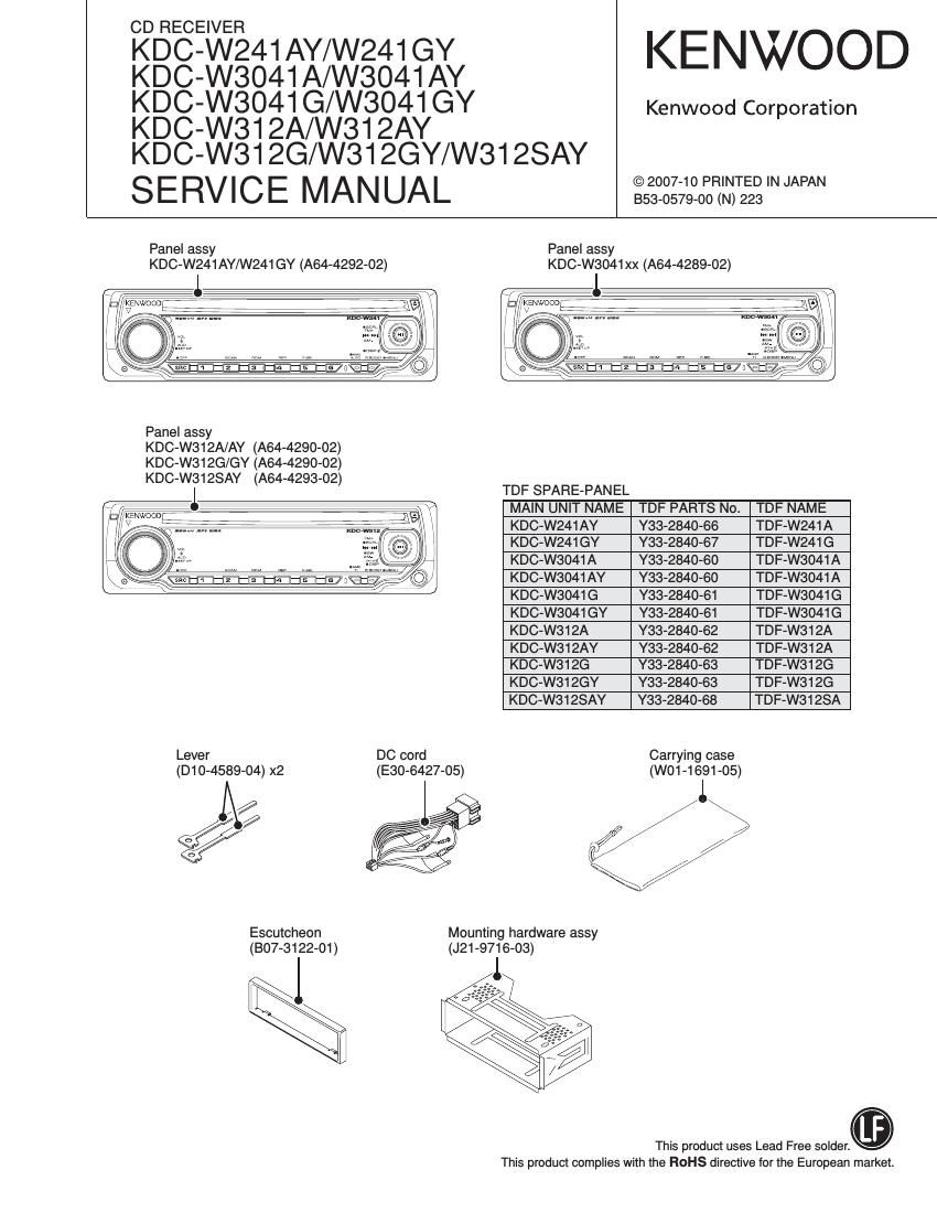
Kenwood KD CW 312 A Service Manual

This is the 40 pages manual for Kenwood KD CW 312 A Service Manual.
Read or download the pdf for free. If you want to contribute, please mail your pdfs to info@audioservicemanuals.com.

Page: 1 / 40
left right
Kenwood KD CW 312 A Service Manual

Extracted text from Kenwood KD CW 312 A Service Manual (Ocr-read)


Page 13

KDC-W24IAY/W24IGY/W304IA/W3041AY/W3041G
/W3041 GY/W3I 2A/W312AY/W312G/W31 2GY/W3128AY

TEST MODE

I MENU-related test mode
Procedure Note

Press the [B.BOOST] key (main unit)
Press the [DNPP/SBF] and [DIRECT] keys (Remote control)

Continuous forwarding by remote control is prohibited

I Backup current measurement

Procedure Note

MUTE terminal is OFF after 2 seconds, not after 15 seconds.

Wh'l ACCOFF B k ON R
'6 ( ac Up ) eset (During this time, the CD mechanism does notfunction.)

I PREOUT switching (except KDC-W241AY/W241GY)

Procedure Note

In the STANDBY source, press and hold [Tl] key for

Switches PREOUT
1 second or longer

I Fluorescent indicator tube (ED1) short check

Procedure Note

All lights are off ~> Turns on odd and even terminals alternatively every
In the STANDBY source, press [ATT] key 125ms (terminals that have a maximum number of grids) ~> Turns on only
the odd terminals ~> Turn on only the even terminals 4)

I Clearing CD mechanism information I Service information / DC offset error information (Clearing EZPROM data)

Status Display Description
While pressing and holding [2] key and E D @ D D D D A normal termination
[5] key, reset-start. @ D D D D D At abnormal termination
While - - -" is displayed, power can be ON for 30 minutes. This mode is cancelled by resetting. (The last screen will not be retained.)

Data to be cleared is shown below.

CD mechanism error log display

Displays CD loading error data

CD mechanism information Displays CD EJECT error data

Displays CD time code count error data (missing count)

Displays CD time code count error data (count not updated)

Power ON time display

CD operation time display

Service Information CD EJECT times display

PANEL open/close times display

Forced Power OFF information display

DC offset error 1 display (Provides information on whether there is an improper connection or another error)
DC offset error information

DC offset error 2 display (Provides information on the number of capacitor leaks)

I Clearing DC offset error detection data (E2PROM data clearing)

Procedure Note

While pressing and holding [3] key and [6] key, reset-start. Entering DC offset error display mode.

13

Page 15

KDC-W241AY/W241GY/W3041A/W3041AY/W3041G

/W304fGY/WSI2A/W312AY/W312G/W312GY/W3128AY
ROM DATA TRANSFER PROCESSES

When replacing front-end (A1) of mother unit (X34) or when
adding or replacing ROM correction (program correction with
ROM IO (ICto)), the following activities are required.

I Overview

When replacing front-end (A1) in the model where ROM
correction and security data have been written into
E2PROM, included in the front-end (A1) pack, the transfer
function of the E2PROM data itself in the replaced front-end
(A1) is required.

This function in the above system configuration is used
to allow for complete replacement of the front-end at any
service center.

I Overview of specifications

Procedures for replacement are as follows: To install the
E2PROM to the mother unit (X34-), and replace front-
end (A1) with new front-end after copying the data in the
E2PROM (such as ROM correction data and other data) in
the front-end (A1) to the mother unit (X34-) by operating the
system, and then copy the data (such as ROM correction
data and other data) into the mother unit to the E2PROM of
the front-end (A1), operating the main body.

Tuner adjustment data was inserted during the tuner pack
manufacturing, and data will not be transferred because
front-end (A1) is built-in.

In addition, tuner adjustment data for new front-end (A1) is
supplied as a service part in which data was inserted.

I Data to be copied
- ROM correction data
- Other data
Security data
DEMO MODE ON/OFF status
POWER ON time (For maintenance)
Playback time (For maintenance)
EJECT count (For maintenance)
Panel open/close count (For maintenance)
CD I2C status (For maintenance)
CD offset error code (For maintenance)
CD sound skips count (For maintenance)
CD time code not updated count (For maintenance)
CD load switch errors count (For maintenance)
CD ejection errors count (For maintenance)
DO offset error (For maintenance)
Forced Power OFF information (For maintenance)
Serial number (For maintenance)
EZPROM data check data (For internal check)

I Operation procedure

Operation procedure is different depending on the conditions.
Proceed with the appropriate operation procedure depending
on the specific condition.

1. In case of replacing front-end (A1) without an applicable
ROM correction.

2. In case of replacing front-end (A1) with an applicable
ROM correction.

3. In case of applying new ROM correction at the same time
when front-end (A1) is replaced. (No ROM correction has
been carried out.)

(1)
Mother unit (X34-)
SYSTEM
FRONT- urCOM (ICI)
END (A1) I
EZPROM EZPROM
/l

E2PROM circuit pattern

Install new E2PROM.

Install E2PROM containing no data, in case of [1] and [2].

In case of [3]. install maintenance E2PROM with an applicable
ROM correction program.

(i)

Mother unit (X34-)

SYSTEM
FRONT- prCOM (IC1)
END (A1)
EZPROM EZPROM

15