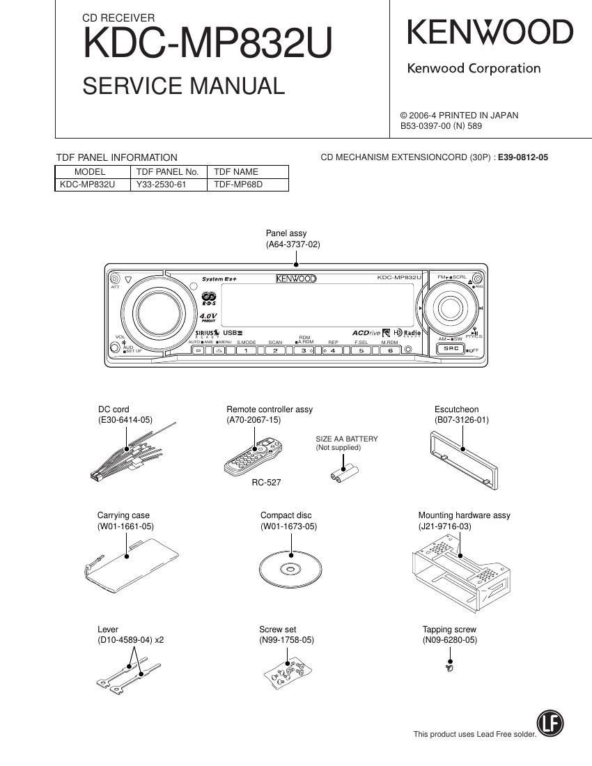
Kenwood KD CMP 832 U Service Manual

This is the 56 pages manual for Kenwood KD CMP 832 U Service Manual.
Read or download the pdf for free. If you want to contribute, please mail your pdfs to info@audioservicemanuals.com.

Page: 1 / 56
left right
Kenwood KD CMP 832 U Service Manual

Extracted text from Kenwood KD CMP 832 U Service Manual (Ocr-read)


Page 15

O MECHANISM MICROCOMPUTER M30620FCPGP (X32-: IC1)

KDC-MP832U

MICROCOMPUTERS TERMINAL DESCRIPTION

Pin No. Pin Name No Application Processing / Operation / Description
1~5 NC - Not used Opened output L fixed
6 BYTE | External data bus SW input Connects to GND
L: Single chip mode
7 CNVSS | Processor mode SW
H: Microprocessor mode or flash ROM writing
8 m 0 Audio mute control L: Mute ON, H: Mute OFF
9 NC - Not used Opened output L fixed
10 W | Reset detection L: Reset (Flash ROM writing), H: Normal
11 XOUT 0 Main clock output Connects to resonator
12 V88 - Power supply input Connects to GND
13 XIN | Main clock input Connects to resonator
14 VCC1 - Power supply input Connects to BU3.3V
15 W | NMI interruption input Input Hi (Pull-up) fixed
16 MSTOP | STANDBY comeback interrupption L: Stop, H: Stop cancelled (Hi edge)
17 NC - Not used Opened output L fixed
18 DSP INT | DSP interruption signal input H: Interruption (Hi edge)
19~22 NC - Not used Opened output L fixed
Series resistors and E2PROM are not built when
23 E2P SCL I/O E2P |2C clock output
ROM collection is not used.
Series resistors and E2PROM are not built when
24 E2P SDA I/O E2P I2C data input and output
ROM collection is not used.
25,26 NC - Not used Opened output L fixed
27 SCL | System u-corn I2C clock input
28 SDA I/O System p-corn I2C data input and output
29 DSP TXD 0 Data output for DSP serial data Flash ROM writing:TXD (Pull-up)
30 DSP RXD | Data input for DSP serial data Flash ROM writing: RXD
31 DSP CLK O Clock output for DSP serial data Flash ROM writing: SCLK(Pu|I-up)
32 DSP STB(BUSY) O DSP data strove signal output Flash ROM writing: BUSY
33 CS SDATA 0 Data output for decoder serial data
34 CS BDATA | Data input for decoder serial data
35 CS CLK O Clock output for decoder serial data
36~38 NC - Not used Opened output L fixed
39 fill - Not used (Flash ROM: EPM) Opened output L fixed
40 PON D3.3 O D3.3V POWER ON control H: POWER ON, L: POWER OFF
41 PON A5 0 A5.0V POWER ON control H: POWER ON, L: POWER OFF
42 PON 031 O |CtS series 3.3V POWER ON control H: POWER ON, L: POWER OFF
43 PON CSZ O |015 series 1.8V POWER ON control H: POWER ON, L: POWER OFF
44 E - Not used (Flash ROM: CE) Opened output L fixed
45 m 0 Driver mute L: Stop, H: Mute OFF
46,47 NC - Not used Opened output L fixed

15

Page 43

KDC-MP832U

W .2";
m I 2 vc
8:; 92%? 3 N 2881443 DAP202U
95:76 DA204K
R64 rm 4 m DA204U
.3 is W 5 w
N W75
5 9:79 a PD DPUt Z
0 9m 7 w (x92) 1%
m
L Dr Sass 3
. 9:... . A
3%... E 2
ESL E
gs; GN" 28A1774 M5237ML-CFOJ
4 l2? @ch 2304081
RUM oat/w Res 099 T war; . WK
DA WW EC 73 K F at its; l5 w
DA 05mm 72 Frt-m. chr 3 2 1
mm av E02 m _ _ _
JL 9:-
|
| 3
I DTA124EUA NJM2100V-ZB
| DT0124EUA
I DTCM4EUA
I our
|
|
I IN
GND
|
|
r lCPlfl I 4
B35 l
C59WOOP I LB1930M-E
csoiunaP
cm W |
ceziunoP |
04 m a z u: s I
[gag S , _I_LI_7 I
, 01: I
v N 9'
a m I 5
@ o I DAN202U TC7SH32FU-F
I M M 5 4
n |
a a | K
3
$3.1; I 1 2
_ _|
7 |
DMZ I 6
QG&SLED J
g: zgmgm CAUTION : For continued safety, replace safety critical components
_ o7 DTCmEE only with manufacturer's recommended parts (reler to parts list).
:2 SS SSTgStRE A Indicates satety critical components. To reduce the risk ot electric
gt? gggafif shock, leakage-current or resistance measurements shall be carried
5 - SIGNAL LINE out (exposed parts are acceptably insulated from the supply circuit)
2 339 fixagggu - (3:ng belore the appliance is returned to the customer.
350 - DC voltages are as measured with a high impedance voltmeter.
3 Values may vary slightly due to variations between individual 7

: instruments or/and units.

X32-5830-00 (4/4) 43