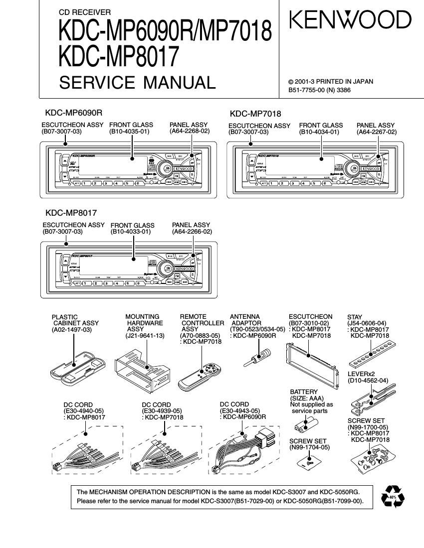
Kenwood KD CMP 8017 Service Manual

This is the 36 pages manual for Kenwood KD CMP 8017 Service Manual.
Read or download the pdf for free. If you want to contribute, please mail your pdfs to info@audioservicemanuals.com.

Page: 1 / 36
left right
Kenwood KD CMP 8017 Service Manual

Extracted text from Kenwood KD CMP 8017 Service Manual (Ocr-read)


Page 7

KDC-MP6090R/MP7018/MP8017

MICROCDMPUTER'S TERMINAL DESCRIPTION

Pin No. Pin Name l/O Description Processing Operation
48-51 NC 0 Not used (N.C.)
52 ILL-ON o Illumination AVR on/ott control output "H'": POWER 0N, "we excel pane] demhej 0'
panel mask posrtron
53 M-MUTE L l Mute request (Lch) from CD MECHA. Ml-COM. "Lo": Mute request
54 m l Mute request (Rch) from CD MECHA. Ml-COM. "Lo: Mute request
55 BVDD - Power supply connection terminal Connected to BU 5V lines.
56 BVSS - Ground connection terminal Connected to GND lines.
57 W 0 Reset output to CD MECHA. MI-COM. "Lo: Reset
58 M-STOP 0 Stop request to CD MECHA. Ml-COM. "Lo": Stop mode, "Hi": Operation mode
59 NC 0 Not used (N.C.)
60 LO/EJ l/O CD MECHA. loading/Eject switching output "Lo": Loading, "Hi": Eject, "Hi-Z": Stop or Break
61 MOSW 0 CD mechanism loading motor control output "Hi": CD loading/eject action or Break, "Lo": other
62 NC 0 Not used (N.C.)
63 CD-SW3 | Down & limit switch detection input "Hi": Chucking, "Lo": Pickup most inner position
64 NC 0 Not used (N.C.)
65 L-CE l/O CE output to LCD driver
66-69 NC 0 Not used (N.C.))
7O AVCONT 0 A/D converter reference voltage control output "Hi": Active, Connected to AVREF terminal.
71 AVDD - AID converter power supply connection terminal Connected to BU 5V lines.
72 AVSS - A/D, D/A converter ground connection terminal Connected to GND lines.
73 AVREF | A/D converter reference voltage input terminal
74 PHONE | PHONE detection input 1V or less: TEL MUTE, 2.5V or greater: NAVI MUTE
75 NC(GND) | Not used (pull down to GND lines)
76 NC(GND) | Not used(pull down to GND lines)
. . . . Panel: (SW1, SW2)=(Hi, Hi)
77 SRT-SW2 l SRT posrtron detection Input Slide: (SW1, SW2)=(Hi, Lo)
78 SRT-SW1 l SRT position detection input Mask : (SW1, SW2)=(Lo, Lo)
79 NOISE l FM noise detection input
80 S-METER l S-meter input from F/E
81 R-DATA | Data input from the RDS decoder lC Except RDS model: Not used (pull down to GND lines)
82 R-QUAL | Quality input from the RDS decoder IC Except RDS model: Not used (pull down to GND lines)
83 IFC-OUT l F/E IFC OUT input terminal "Hi": Station detected, "Lo": Not detected
84 NC(GND) | Not used (pull down to GND lines)
85 NC(GND) | Not used (pull down to GND lines)
86 NC 0 Not used (N.C.)
87 R-CLK l Clock input from the RDS decoder IC Except RDS model: Not used(pull down to GND lines)
88 CH-REQC | Request input from changers "Lo": Request
89 KEY-REQ | Communication request input form LCD driver IC
90 CD-SW1 | Loading detection "Lo": CD chucking.
91 CD-SW2 l 12cm disc detection terminal When 12cm disc was detected, the input becomes
"Lo" temporarily.
92 NC 0 Not used (N.C.)
93 WT l Momentary power down detection input "HI" : When momentary power down detected or BU OFF
"Lo" : BU ON
94 CH-DATAC | Data input from changers
95 CH-DATAH 0 Data output to changers
96 CH-CLK l/O Clock input/output with changers
97 L-DATAL | Data input from the LCD driver IC
98 L-DATAS l/O Data output to the LCD driver IC
Clock output to the LCD driver IC/Panel .. u
99 LCLK I/O detaching detection input (LCD Driver) Lo : Panel attached
100 PAN5V 0 Panel 5V control "Hi": Panel attached, "Lo": Panel detached

Page 13

KDC-MP6090R/MP7OI8/MP8017

CIRCUIT DESCRIPTION (MP3)

0 PCM output Interface
The decoded audio data are output in serial PCM format.
The interface consists of the following signals.

ADO PCM Serial data Output
SCKT PCM Serial Clock output
LRCLK Left/right Channel selection Clock

The output samples preciision is selectable from 16 to 24
bits/word, by setting the output precision with PCMCONF
(16, 18, 20 and 24 bits mode) register. Data can be output
either with the most significant bit first (MS) or least signifi-
cant bit first (LS), selected by writing into a flag of the
PCM-CONF register.

Figure 5 gives a description of the several STA013 PCM
Output Formats.

The sample rates set decoded by STA013 is described
Table 1.

16 SCLK 16 SCLK 16 SCLK
Cycles Cycles Cycles
15 SCLK 16 SCLK
LRCKT Cycles Cycles
M L M L M L M L PCM one
SDO Is sl 5 sIs sIs s FCM:PRE(:IISblImode
L M L M L M L M FCM one:
SDO Is sIs sIs sIs s PCM:FRECI=16bllmode
32 SCLK 32 SCLK 32 SCLK
Cycles 32 SCLK Cycles 32 SCLK Cycles
LFtCKT Cycles Cycles
M L M L M L M L PchonMArel
SDO I 5 SI 0 I 5 SI 0 Is SI 0 Is sI D PCMJlFFel
M L M L M L M L PchonMAreo
500 I ° Is sI ° Is s| ° Is 5| ° Is 3 mm»...
M L M L M L M L pchonMAreo
SDO HS sI D I°Is sI ° I°Is SI 0 H5 sl 0 PCMJlFFel
M L M L M L M L FCM FORMAT:
SDO I MSB Is sI M55 I s sI SE Is sI SB Is 5 PCM:DIFF=D I
Fig. 5 PCM output Formats
MPEG1 MPEG 2 PMEG 2.5
48 24 12
44.1 22.05 11.025
32 16 8

Table 1 MPEG Sampling rates (kHz)

0 STA013 Operation Mode

The STA013 can work in two different modes, called
Multimedia Mode and Broadast Mode.

In Multimedia Mode, STAO13 decodes the incoming bit-
stream, acting as a master of the data communication from
the source to itself.

This control is done by a specific buffer management, con-
trolled by STA013 embedded software.

The data source, by monitorng the DATAiFiEQ line, send
to STA013 the input data, when the signal is high (default
configuration).

The communication is stopped when the DATAiREQ line
is low.

In this mode the fractional part of the PLL is disabled and
the audio clocks are generated at nominal rates. Fig. 9
describes the default DATAiREQ sigal behaviour.
Programming STAO13 it is possible to invert the polarity of
the DATAiREQ line (register REoiPOL).

SOURCE STOPS
TRANSMITTING DATA

DATAfiEQ m

SOURCE SEND DATA TO STA013
Fig. 6

SOURCE STOPS
TRANSMITTING DATA

In Broadcast Mode, STA013 works receiving a bitstream
with the input speed regulated by the source. In this config-
uration the source has to guarantee that the bitrate is
equivalent to the nominal bitrate of the decoded stream.
To compensate the difference between the nominal and
the real sampling rates, the STA013 embedded software
controls the fractional PLL operation. Portable or Mobile
applications need normally to operate in Broadcast Mode.
In both modes the MPEG Synchronisation is automatic and
transparent to the user. To operate in Multimedia mode,
the STA013, pin nr. 8, SCR-INT must be connected to
VDD on the application board.

0 STA013 Decoding States

There are three different decoder states: Idle, Init, and
Decode. Commands to change the decoding states are
described in the STA013 IZC registers description.

- Idle Mode

In this mode the decoder is waiting for the RUN command.
This mode should be used to initialise the configuration regis-
ter of the device. The DAC connected to STAO13 can be ini-
tialised during this mode (set MUTE to 1).

PLAY MUTE Clock State PCM Output
X 0 Not Runnig 0
X 1 Runnig O 1 3