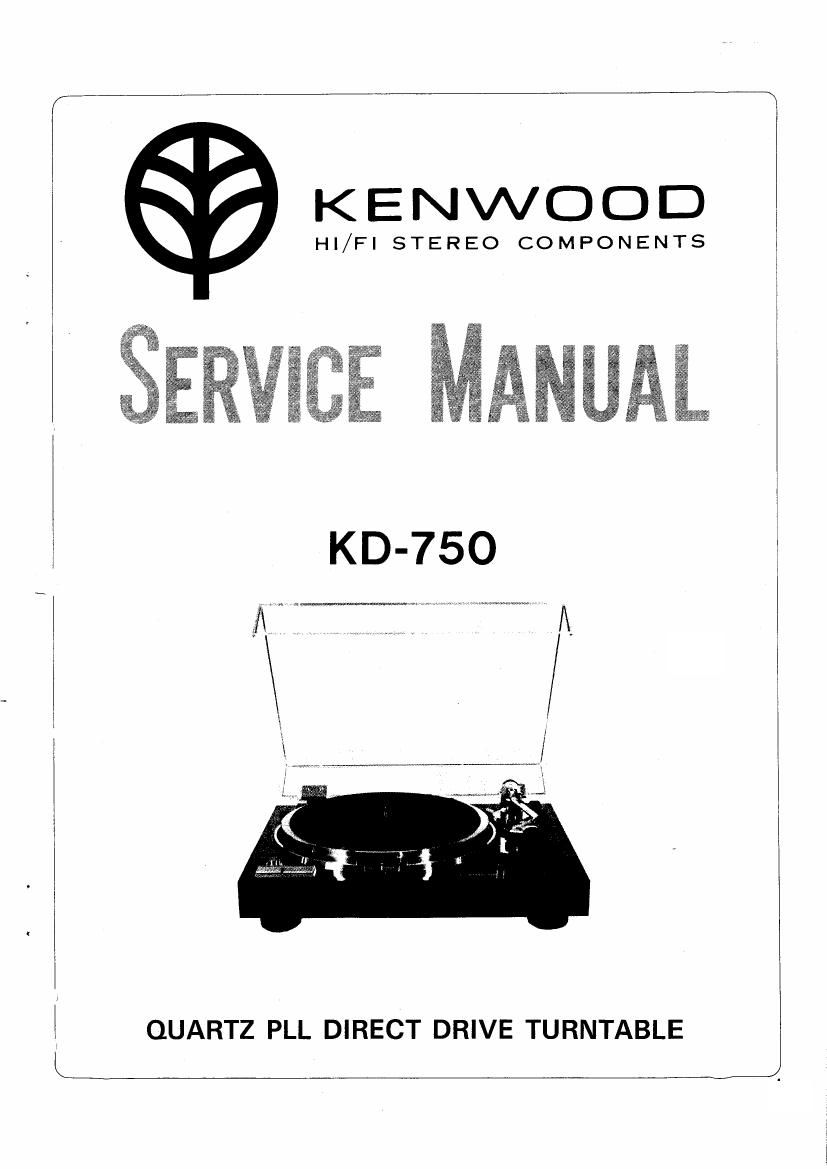
Kenwood KD 750 Service Manual

This is the 52 pages manual for Kenwood KD 750 Service Manual.
Read or download the pdf for free. If you want to contribute, please mail your pdfs to info@audioservicemanuals.com.

Page: 1 / 52
left right
Kenwood KD 750 Service Manual

Extracted text from Kenwood KD 750 Service Manual (Ocr-read)


Page 1

KENWOOD

Hl/FI STEREO COMPONENTS

QUARTZ PLL DIRECT DRIVE TURNTABLE

Page 2

CONTENTS

EXTERNAL VIEW ............................................................................................... 3
INTERNAL VIEW. 4
BLOCK DIAGRAM ............................................ 5
MOTOR CIRCUIT DESCRIPTION ...................................................................... 5
LOGIC CIRCUIT DESCRIPTION ........................................................................ 16
TONEARM DESCRIPTION ................................................................................. 26
HEAD SHELL... 32
AUDlO CORD ....................................................... .. 34
TURNTABLE SHEET ........................................................................................... 34
DISASSEMBLY FOR REPAIR ............................................................................ 38
ADJUSTMENT .................................................................................................... 40
EXPLODED VIEW.. 42
EXPLODED VIEW PARTS LIST ......................... 43
DESTINATIONS' PARTS LIST ............................................................................ 44
PARTS LIST ....................................................................................................... 45
PACKING ............................................................................................................ 46
REVISED CIRCUIT.,. .......................................................... 46
TROUBLESHOOTING ..................................... .. 47
PC BOARD ......................................................................................................... 50
SCHEMATIC DIAGRAM ..................................................................................... 51

SPECIFICATIONS .......................................................... .................................... 52

Page 26

TONEARM

Two blg problems on tonearrn are tonearrn resonance
curve and partial resonance caused by lack of stiffness of
components.

Tonearm Resonance

A baSIC equivalent Circuit of tonearm for a low frequency
range is as shown In Fig, 3A1. This equwalent olrcun
resonates at f0:

1 s 1
L: x a: . ............... l)

2 m' 27ry'mt-Ca

58:".-
Ca
V0 _. mi
ra rl
Zm

Sa
Vo' Veloclty amplitude of record groove
Zm Mechanlcal impedance in view or stylus

5a, ra Equivalent stiffness and resistance or support of
Vibration system.

rm. Equivalent mass of tonearrn included cartridge

rt Equivalent resrstahce of tonearrn fulcrum.

Equivalent circuit of pickup in low freq.

Fig. 3-1

This resonance rs the tonearm resonance, 0 indicating
sharpness of resonance peak is given as;

_ 2 .7 17/. gm
ra+rt

Q (2]

Generally. it is said thatfo should be in 7 ~ 12 H2. so that
noise caused by bend of disk and the turn of the motor is
eliminated Frequency characteristics and mechanical im-
pedance characteristics in the case where Ca. rm and Q are
changed are shown in Fig. 3-3 to 3-5.

Disk
. i0

OdBilcmsPeak iocr rnplltude

a ' 20

E

E

>

.9 30

D

:

n:

.o

E 40

m

2
. 50 x

be

60

4 B 8 l0 2 4 5 BIUU
fin)

Frequency us bent disk

Fig. 3.2

In Fig 3-3, variation of Ca corresponds to replace car»
tridge When value of Ca is large. the cartridge is a high
compliance one. When value of Ca is small. a low come
pliance one. As known from eq. (1). tonearm resonance fo
decreases as the value of Ca increases

20
I ll
Ca 2
lo Ca
A 20 Li
a
E 0 ~ E
3
.:
3 lO
w
H;
II
,20

0
ssorz 468i 2 463m 2
Frequency (fl)

Frequency characteristic when changing the value of ca.

2(0:2.22

Nha

OaiO=2l


I
2 E CaQ=l4l)
73 A
E
g z
3

in
E 8
s
4
2

580.12 4 63'

Z 4 E 8 i0 2
Frequency (fi)

Mechanical impedance when changing the value of Ca,

Fig, 3-3