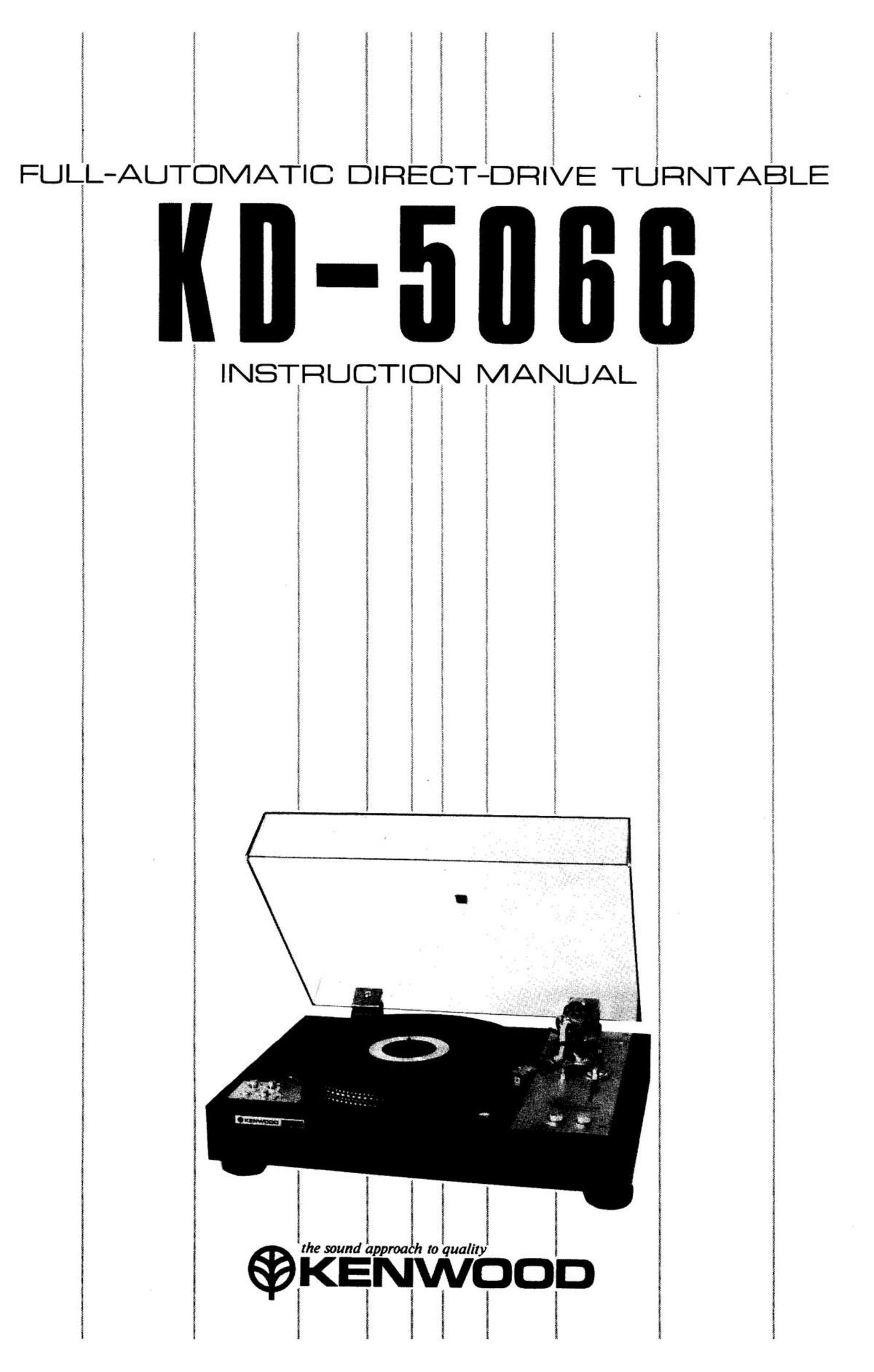
Kenwood KD 5066 Owners Manual

This is the 12 pages manual for Kenwood KD 5066 Owners Manual.
Read or download the pdf for free. If you want to contribute, please mail your pdfs to info@audioservicemanuals.com.

Page: 1 / 12
left right
Kenwood KD 5066 Owners Manual

Extracted text from Kenwood KD 5066 Owners Manual (Ocr-read)


Page 2

INTRODUCTION

Thank you for purchasing our turntable.
Because we take great pride in the long tradition of
quality components the name KENWOOD repre
sents, your choice of our product places you in a
distinguished family of connoisseurs of superb high-
fidelity sound reproduction.

The purpose of this manual is to acquaint you
with the operating features of your new turntable.
You will notice that in every detail of planning,
engineering, styling, operating convenience, and
adaptability, we have sought to anticipate your
needs and desires.

We suggest that you read this manual carefully.
Knowing how to set up your turntable, to the best
advantage, will enhance your listening pleasure
right from the start. You will also become aware
of the ease with which you can adjust your turn-
table to meet your special requirements.

Turn the pages and become acquainted with
the exciting features of your new turntable, fea
tures that will remain new for endless hours of
listening pleasure.

SERIAL NUMBER

Record your SERIAL NUMBER on the spaces
designated on the warranty card. You will find the
serial number on the back of the unit.

CONTENTS

INTRODUCTION ......................... 2
FEATURES ............................ 2
NOTES ................................ 3
ASSEMBLY PROCEDURE .................... 5
STYLUS PRESSURE ADJUSTMENT ........... 5
OPERATING INSTRUCTIONS ................ 6
HOW TO ADJUST

THE TURNTABLE SPEED .................. 8
HOW TO ATTACH THE CARTRIDGE .......... 8
MAINTENANCE .......................... 9
TROUBLE SHOOTING ..................... 11
SPECIFICATIONS ........................ 12

FEATURES

1. Direct Drive System
The direct drive system with 20 pole 30 slot
DC servo motor is excellent both in wow and
flutter and rumble, providing great reliabil-
ity which leads to longer life of your turn-
table.

2. Stroboscope with Lamp
Stroboscope stripe patterns are etched into the
outer rim of the turntable platter to enable
speed accuracy checks. And the correct speed
can be obtained by turning the speed adjusting
knob.

3. Reliable Full Automatic Mechanism
This is a fully automatic turntable that only
requires the operator to place a record on the
platter and press a button. It can also be used
manually, if desired.

4. Static-Balance Type Tonearm
S-shaped static-balance type tonearm is equip-
ped with an Anti-Skating Device that is adjust-
able during record play.

5. KENWOOD Cartridge V-41A
The cartridge V-41A is V-shaped dual magnet

type.

6. Woody Cabinet Adopting ARCB Together
* ARCB = Anti-Resonance Compression Board

7. Free-Step Action Dust Cover

8. Large Insulator Legs ensure excellent cushion
effect to prevent acoustical feedback.
The turntable can be easily installed level
using the Level Indicator and the adjustable
insulator legs.

9. Pause Mechanism enables temporary interrup-
tion of record play when desired.

10. Provided with Shell Stand for keeping extra
head shell.

11. Low Capacitance Phono Cable

WARNING:

TO PREVENT FIRE OR SHOCK
HAZARD, DO NOT EXPOSE THIS
APPLIANCE TO RAIN OR MOIS-
TURE.

Page 8

HOW TO ADJUST
THE TURNTABLE SPEED

Stroboscope stripe patterns are etched into
the outer rim of the turntable platter to enable
speed accuracy checks. As shown in Fig. 9, the 4
stripe patterns are selected according to the power
supply frequency and turntable speed to be used.

When the turntable is rotating at a correct
speed, the selected stripe pattern illuminated by
the strobo lamp should be viewed as if it were not
moving. If the stripe pattern is moving in the direc-
tion of the turntable rotation, it means that the
turntable speed is fast, and in the opposite direc-
tion the turntable speed is slow.

In either case, the correct speed can be obtain-
ed by turning the speed adjusting knob in the
opposite direction of the movement of the stripe
pattern until it stops moving.

Fig. 9 shows an example of speed adjustment
for 33-1/3 r.p.m. at 60 Hz.

NOTE:

Adjustment procedure is as follows:
Set the size selector to "MANUAL" position and
press the "PLAY" button to rotate the turntable
platter, then check the stripe pattern movement
and make an adjustment if necessary.

You could perform the adjustment even when
a record is being played.

33% r.p.m. at 60Hz

- Turntable Platter revolving direction
In rl

l! I '. ' 1
l' .1 j'

«Stroboscope drift direction=1>
Faster SPEED 33,5:Er.p.m. Slower

Fig. 9 How to Adjust the Speeds

HOW TO ATTACH
THE CARTRIDGE

Cartridge can be attached easily as follows:
The tonearm uses EIA standard connectors that
can accept any head shell on the market that con-
forms to this standard.

1. Connect four leads to the cartridge, as shown
in Fig. 10.

2. Attach the cartridge to the head shell but
keep the two screws slightly loose so that the
cartridge can be shifted forward or backward
as desired. Use appropriate length screws.
Slip the over-hang gauge over the head shell
as shown in Fig. 11, and move the cartridge
so that the stylus point lines up with the
gauge arrowmarks. Now tighten the cartridge
locking screws. This completes correct stylus
over-hang adjustment for this turntable.

3. Plug the head with the cartridge into the tone-
arm, readjust stylus pressure, as explained on
page 5 so that it conforms to the cartridge
manufacturers recommendation.

Cartridge can be replaced easily by removing
the old one and attaching the replacement in the
above manner.

NOTE:

Usable cartridge weight 4 ~ 12 grams.

Screws

Washers

Head Shell

Cartridge WHITE l_( +)
RED R( +)

Nuts BLUE L( E)
GREEN R( E)

Fig. 11 Over-Hang Gauge

Page 9

NOTES:

1.

Correct height of arm elevation and arm rest
is important. When a cartridge or head shell
is changed, it is important to check the follow-
ing before operating the turntable.

During record play, the tonearm must never
touch the arm elevation. Also stylus must
never touch the record surface when the tone-
arm swings horizontally during automatic ac-
tion.

If corrective measures are found necessary,
proceed as follows. Set the pause lever to 1
position. Adjust space between stylus point
and record surface to approximately 6 mm
with the locking bolt @as shown in Fig. 12.
Next adjust the height of the arm rest to cause
a gap of about 1mm between the tonearm
and arm elevation with the bo|t®.

Jess .

6~|8mm

Fig. 12 Height of Elevation and Rest

Connection to stereo amplifier (Receiver)

To use the turntable with your amplifier, con-
nect the output cords and the GROUND lead
of the turntable to the PHONO jacks and the
GND terminal of the amplifier, respectively.

0 When a low output, moving coil (MC) type
cartridge is used, connect a step-up transform-
er or an amplifier designed for use with MC
type cartridges.

0 If a non-standard cartridge is used, connect it
to the amplifier by following the instruction
manual for the cartridge.

MAINTENANCE

STYLUS LANDING POSITION ON LEAN-IN
GROOVE OF RECORD

This adjustment has already been made at the
factory but may require fine readjustment depend-
ing on the cartridge that is used. To make this
adjustment see Fig. 13. Set the size selector to
position "30". Insert a + screwdriver into the Auto
in adjust hole and turn the adjustment screw. Turn-
ing it clockwise will move the stylus landing point
inwards, and counterclockwise, outwards.

The landing point will move about 1 mm for
each complete turn of the adjustment screw.

Do not remove
the screw in
this hole.

I.)
(L/
I Auto-in Adjust hole.

Fig. 13 Adjusting the Stylus Landing Position

ADJUSTING THE STOP-ACTION OF
THE COVER

The dust cover for this turntable has a free
stop action. If it should close abruptly, the stop-
sction can be strengthened by turning the hinge
screw counterclockwise as shown in Fig. 14 (both
hinges).

/ ///fl/ Ir/fl, /,,. ,/ [oz/{4 ,2: // /:/x;2/),' [WW 4,// 7 \

i w!
. ' . //I i
\ 3 , . -

Fig. 14 Adjusting the Stop-Action of the Cover