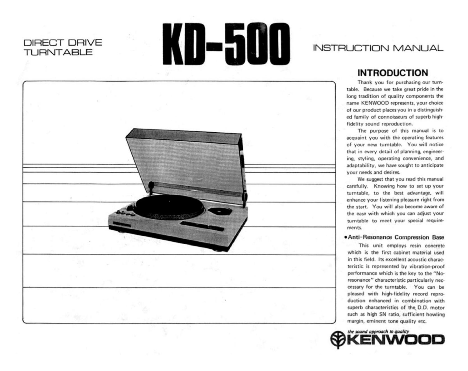
Kenwood KD 500 Owners Manual

This is the 4 pages manual for Kenwood KD 500 Owners Manual.
Read or download the pdf for free. If you want to contribute, please mail your pdfs to info@audioservicemanuals.com.

Page: 1 / 4
left right
Kenwood KD 500 Owners Manual

Extracted text from Kenwood KD 500 Owners Manual (Ocr-read)


Page 1

DIRECT DRIVE
TURNTABLE Kn- 5 INSTRUCTION MANUAL

an, .4, e . v P",
-m_;_ jinn..- -
~ Hyu U .

INTRODUCTION

Thank you for purchasing our turn-
table. Because we take great pride in the
long tradition of quality components the
name KENWOOD represents, your choice
of our product places you in a distingursh-
ed family of connoisseurs of superb high-
fidelity sound reproduction.

The purpose of this manual is to
acquaint you with the Operating features
of your new turntable. You will notice
that in every detail of planning. engineer-
ing, styling, operating convenience. and
adaptability, we have souwt to anticipate
your needs and desires.

We suggest that you read this manual
carefully. Knowing how to set up your
turntable. to the best advantage, will
enhance your listening pleasure right from
the start. You will also become aware of
the ease with which you can adjust your
turntable to meet your special require-
ments.

OAnti-Resonance Compression Base

This unit employs resin concrete
which is the first cabinet material used
in this field. Its excellent acoustic charac-
teristic is represented by vibration-proof
performance which is the key to the "No
resonance" diaracteristic particularly nec
cessary for the turntable. You can be
pleased with hiQt-lidelity record repro
duction enhanced in combination with
superb characteristics of the 0.0. motor
such as hiw SN ratio, sufficient howling
margin, eminent tone quality etc.

REWNVVO " on

Page 2

UNPACKING AND SETTING-UP

I.

l
Refer to Fig. 2 and confirm that all parts are
correctly furnished. (Fig. 2: Location of Parts)
Remove, without fail, screws for fixing the power
trenslormer ior protection during transport.
(Fig. 3: Fixing Screws)
You can mount your favorite tone arm on the
attached arm base. This unit provides for the
two types of arm bases, either of which can be
selected according to the type of tone arm to
be mounted. Regarding the methods of mount-
ing the tone arm and usage, please refer to the
attached instruction manual for the tone arm.
Gently put the turntable on the table shaft and
then put the rubber sheet on it.
Mount the dust cover (Fig 4).

Transformer filing act-we for
protection during tranport.

(Two acrewa must be
moved without fall.)

Fig. 3 Fixing Screws

L

Vi? ,

Fig. 4 Installation of Dust Cover

CONNECTIONS

Insert the AC cord plug in the wall outlet or the
AC outlet of the amplifier unit.

In this case, AC voltage must be checked with-
out fail.

Connect the ground terminal of the main body
between the GNU terminal of the amplifier by use of
the furnished ground wire.

Regarding the audio cord connections, please
refer to the instruction manual of the purchased tone
arm. Fig. 5 shows an example of audio cord connec-
trons.

Audio cord
Ground wire

Stored mliflor

AC OUYLEI'

. , ono 0E0


Ground wire

Fig. 5 Amplifier and Connections

PLACE FOR INSTALLATION

In order to use the unit under the best condition.

the following points should be borne in mind:

I.

2.

Install the unit horizontally in a stable place
where no external vibration may occur.

The unit should not be exposed to a direct sun
beam or high temperatures which may be caused
by room heaters. etc.

Perfect performance characteristics cannot some-
times be assured where an ambient temperature
is extremely low (below 0°C).

The unit should not be installed where dust and
moisture are prevalent and wind passage is in-
eIIective.

Install the unit as far lrom the speaker systems
as possible. Such installation may suppress the
occurrence of howling.

Where horizontality cannot be obtained, the legs
of this unit should be turned to the ridit or left
for the adiustment of heidit to obtain a better
horizontality. (In order to increase the effect of
insulators. respective legs should be loosened after
rotating four times when adjusting heimt of the
unit I

L File Installation of one Arm J

r. the attached hexagon-head
wrench and install Ute embaee