Kenwood KAV 5500 Service Manual

This is the 38 pages manual for Kenwood KAV 5500 Service Manual.
Read or download the pdf for free. If you want to contribute, please mail your pdfs to info@audioservicemanuals.com.

Page: 1 / 38
left right
Kenwood KAV 5500 Service Manual

Extracted text from Kenwood KAV 5500 Service Manual (Ocr-read)


Page 1

m STERK-i7§500/7500 KENWOOD?

SERVICE MANUAL

©1990-10 PRINTED IN JAPAN
BS1-4207-OO(S)1541

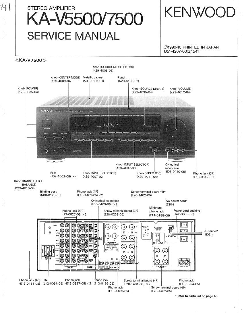
< KA-V7500 >
Knob (SURROUND SELECTOR)
(K29-4008-03)
Knob (CENTER MODE) Metallic cabinet Panel

(K29-4009-04) (A01-1805-01) (A20-6103-02)

Knob (POWER) Knob (SOURCE DIRECT) Knob (VOLUME)
(K29-3835-O4) (K29-4035-O4) (K29-4012-O4)

Knob (INPUT SELECTOR) Cvlindrical
(K29-4037-03) receptacle

Foot Knob (INPUT SELECTOR) Knob (VIDEO REC) (5060410'05 Phono jack (3P)
(J02»1002-05) ><4 (K29-4007-O3) (K29>4011-O4) (E1 3-0312-05)
Knob (BASS, TREBLE,
BALANCE)
(K29-4010-04)
Binding post Phono jack (4P) Screw terminal board (4P)
(N08'0128»35) (E13-140205) X2 (E20-1402-05)
Cylindrical receptacle AC power cord
(EOE-0409-05) X2 (E30-)
Miniature
Phono jack (8P) Screw terminal board (2P) phone jack Power cord bushing
(13»0827-05) ><2 (E20-0238-05) (51 1018305, (J42.0083-05)

©©
@@

D" 3',

AC outler
(EO3-l


PhonojackMPl PIN Phonojack Phonojack Screwterminal board (4P) Phono jack

(EB-043305) (J12-0091-05) (E13-0827-05)><2 (E13-0192-05l (£20.14o1.05) x2 (93.025405)
Phono jack Screw terminal board (4P)
(334403-05) lE20-1402-05)

' Refer to parts list on page 43.

Page 7

KA-V5500/75OO % '
CIRCUIT DESCRIPTION

Pin Functions
,uPD75216Acw-B40

Pin No, Pin Name 1/0 Name Description
1 SO 0 Segment (1 FL segment signal
2 82 0 Segment c FL segment signal
3 - S1 0 Segment b FL segment signal
4 So 0 Segment a FL segment signal WWW a (7 WWW W" F
5 POO/INT4 I KRO Key Return 0
6 FONS? O lMPCLK Serial clock for superimpose
7 POZ/SO O IMPSI Serial data for superimpose
8 P03/Sl 1 fi Power failure detection (0 Power fallure)
9 P10/INTO l REMllVl Remote control input (interrupt)
10 P11/INT1 l KR1 Key Return 1
11 P12/INT2 l KR2 <<<<< "kg; Return 2 7
12 P13/TlO l __ KR3 Key Return 3
13 P20 l ROTRYO NC
14 P21 1 ROTRYi NC WWI.
15 P22 1 EEP ~ DI EEPROM serial data lnput
1e P23/BUZ l BTL NC
17 P30 5 EEP - DO EEPROM serial data output
18 P31 6 EEPCLK EEPROM serial Clock
19 P32 v5 SBUSY External serial communication busy Slgnal MN-
20 P33 1/5 SDATA External serial communication data Signal
21 P60 6 0 Extension l/O (M50791sP) control signal
22 P61 5 ,_ Vii/Wm, LA Extension l/O (M50791SP) control signal
23 P62 6 E Extension l/O (M50791SP) control signal
24 P83 6 R-ES Extension I/O (M50791SP) control signal
25 P40 5 VOLDI Serlal data for digital delay, rear volume and center volume
26 P41 5 VOLCLK Serlal Clock for digital delay, rear volume and center volume
27 P42 5 Serial or audio lLC7821/22) and surround (TC9162/63)
28 P43 6 Seriaic DC for audio (LC7821/22) and surround (TC9162/63)
29 PPO 6 Power ON/OFF relay control 11* ON)
30 X1 # Microprocessor system clock oscilylatlon pin M
31 X2 - - Microprocessor system clockvoscillatlon pin .7 W
32 vSS - - GND
33 > 34 XTZ ~ - Mlcroprocessor subolock oscillatlon pin (unused) i
35 P50 5 PRO Extension l/O (M50791SP) data signal
36 P51 5 PR1 Extension I/O (M50791SP) data Slgnal
37 P52 6 PR2 Extension I/O (M50791SP) data signal M
38 P53 6 PR3 Extension |/O (M50791SP) data signal H M
39 W - - Reset input
40 T0 5 36,116 FL digit signal
41 T1 5 16 FL digit signal
42 T2 5 16 FL diglt signal
43 13 6 10(3 FL digit signal
44 14 6 so FL digit signal
45 T5 6 so FL digit signal 7