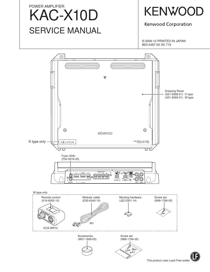
Kenwood KACX 10 D Service Manual

This is the 20 pages manual for Kenwood KACX 10 D Service Manual.
Read or download the pdf for free. If you want to contribute, please mail your pdfs to info@audioservicemanuals.com.

Page: 1 / 20
left right
Kenwood KACX 10 D Service Manual

Extracted text from Kenwood KACX 10 D Service Manual (Ocr-read)


Page 2

KAC-X1OD

LEVEL DriSdB
FREQ 407i OOHZ

BLOCK DIAGRAM

ICI SENS. L69
L LSOVAMP IC4 (l/2I VOL Ic4 (2/2) Ic5 (2/2).6.7 LCB i F5
BASS I ' '
m JURMIXH # BOOSTH LRF I ;::z ISSELF
R ISOVAMP ' L z


FREQ
,5 (411720on)

-o- - I
Lcm (2/2) Lou LCMJE om osru : o7mr704
SUMMLNG DEAD LEVEL FINAL
AMP COMP H TIME I-ISHLET I-I DRVE I-Il MOSVFET 5
41 I + 9;:
LCiOII/Z) L013 LCIS 15 01415 01619 I {27057703 LC F'LTER - 8E
TRIANGLE DEAD LEVEL FINAL EL
IWAVE COMP H TIME Iif SHIFT '| ME I 'IMOSVFET
I aoowmo
L012 I/Z) I BELOW/20
(15.22 I LCI7 soow / L Q


K224 |

IC37

THERMAL
DET

iiinrCON

L
L
L
POWER L
L
L
L
L

to
{23197322 I I
:isv E,
AVR *3 BA
:0 GND

COMPONENTS DESCRIPTION

0 AUDIO UNIT (X09-8590-1 0)

Rel. No. Application / Function Operation / Condition / Compatibility
|C1,2 Isolation AMP Removai of common mode noise on input signal
|C3 Buffer AMP Buffer AMP for RCA output
|C4 Mixing AMP and buffer AMP It mixes input stereo signals into monaural signals. GA|N=0dB
It boosts signals by the operation 01 the remote control.
|CS~7 Bass Boost circuit (remote control operation)
GA|N=O~+18dB, fc=40~100HZ
|C8 L.P.F 40~200Hz -24dB/oct
ICQ |.S.F OFF/15HZ/25HZ switchable ~24dB/oct
|C1O D-class phase input AMP
Generation of triangular wave, and generation of PWM signal by
|C11 PWM signal generating circuit
comparing triangular and sine wave.
|C12 Triangular wave reversal and DC servo circuit It feeds back the triangular wave reversal and DC voltage offset.
Circuit to generate PWM signal by comparing triangular and sine wave.
|C13 PWM signal generating circuit and Iatch circuit
Circuit to latch when 19 load is detected.