Kenwood KAC 820 Service Manual

This is the 17 pages manual for Kenwood KAC 820 Service Manual.
Read or download the pdf for free. If you want to contribute, please mail your pdfs to info@audioservicemanuals.com.

Page: 1 / 17
left right
Kenwood KAC 820 Service Manual

Extracted text from Kenwood KAC 820 Service Manual (Ocr-read)


Page 1

STEREO POWER AMPLIFIER

KAC-820

SERVICE MANUAL

C1988-I PRINTED IN JAPAN
851-3443-OO(B)2496

§
3
z
LU
:4
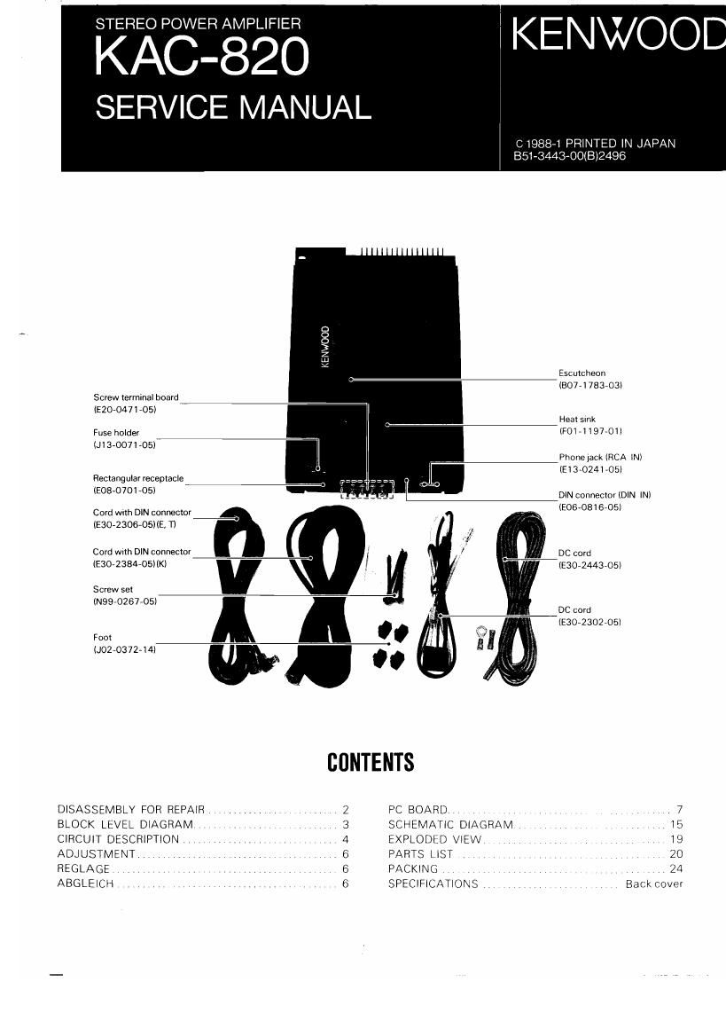
Escutcheon
(807- I 783-03)
Screw termmal board 77
IEZO-0471-05I
Heat smk
Fuse holder IF0171197701)
IJI 3-0071'05I

Phonejack (RCA lNI
IE13-0241-05I
Rectangular receptade

IE08-O701-05I DIN connector IDIN INI

Cord with DIN connector (£06.08 I 605
530230605) (E, T)
Cora wnh DIN connector DC cord
IE30-2384-05IIK) IE30-2443»05I
Screwset
IN9970267705I
DC cord
IE3O-2302A05I
Foox
(J02A0372-14I
DISASSEMBLY FOR REPAIR, 2 PC BOARD . ,. , .. . 7
BLOCK LEVEL DIAGRAM 7 V 3 SCHEMATIC DIAGRAM . .. , I5
CIRCUIT DESCRIPTION . 4 EXPLODLD VIEW V V . .. V V 19
ADJUSTMENT. , 6 PARTS LIST , . ., , _ , 20
REGLAGE . I 6 PACKING V , 24
ABGLEICH 6 SPECIFICATIONS Back cover

Page 2

AC-82

DISASSEMBLY FUR REPAIR

1. Remove the 5 screws ( o ) from the bottom cover
2. Remove the 3 screwst o ) from the rear panel.
3. Removethez screws( 0 )from thetront panel.

4. Remove the 6 screws( 0 ) from the PC Board.
5. Me|t the solder fixtng the screw ( 0 ). and remove the
screw using a screwdriver.

6 Disconnect connectors CN1 and CN2( G ).
7. Disconnect connector CN4. and remove the PC Board in

the direction of the arrow ( O )

8 Remove the6 screws( 0 )from the PC Board
9. Remove the PC Board on which the diode is mounted, by
pushing the tug on the PC Board in the direction of the

arrow( 9 )