Kenwood KAC 646 Owners Manual

This is the 16 pages manual for Kenwood KAC 646 Owners Manual.
Read or download the pdf for free. If you want to contribute, please mail your pdfs to info@audioservicemanuals.com.

Page: 1 / 16
left right
Kenwood KAC 646 Owners Manual

Extracted text from Kenwood KAC 646 Owners Manual (Ocr-read)


Page 1

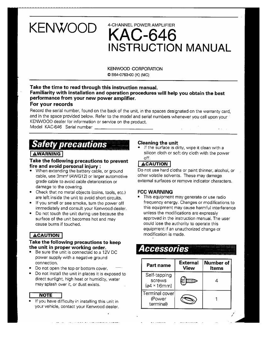
KENWOOD KACW-646
INSTRUCTION MANUAL

KENWOOD CORPORATION
O 864-07630!) (K) (MC)

Take the time to read through this instruction manual.

Familiarity with installation and operation procedures will help you obtain the best
performance from your new power amplifier.

For your records

Record the serial number, found on the back of the unit, in the spaces designated on the warranty card,
and in the space'provided below. Refer to the model and serial numbers whenever you call upon your '
KENWOOD dealer for information or service on the product.

Model KAC-GAG Serial number

Cleaning the unit

safety precautions, : , ,_ ., - if the surface is dirty, wipe it clean with a
AWARNING silicon cloth or soft dry cloth with the power

off.

Take the followrng precautions to prevent ACAUTION

fire and avoid personal injury :

0 When extending the battery cable, or ground Do not use hard cloths or paint thinner, alcohol, or
cable, use 3mm (AWE-312) or larger automotive other VOIEU'E solvents. These may damage
grade cable to avoid cable deterioration or external surfaces or remove indicator characters,
damage to the covering.
0 Check that no metal objects (coins. tools, etc.) FCC WARNING
are left inside the unit to avoid short circuits. ' This equipment may generate or use radio
. |f you smell or see smoke, turn the power off frequency energy. Changes or modifications, to
immediately and consult your Kenwood dealer. This SqUiPment may CBUSe harmful Interference
Do not touch the unit during use because the unless the modifications are GXDFESSIV
surface of the unit becomes hot and may approved in the instruction manual. The user
cause burns if touched. could lose the authority to operate this
equipment if an unauthorized change or
modification is made.

Take the following precautions to keep

the unit in proper working order.
- Be sure the unit is connected toa 12V DC

power supply with a negative ground E | N b f

connection. , P xterna um er 0
art name .

Do not open the top or bottom cover. "" VIeW Items

Do not install the unit in places it is exposed to se[f_tapping

direct sunlight, high heat or humidity, water screws

may splash over it, or dust exists. . (g4 x 16mm)

Terminal cover
$5 1

o If you have difficulty in installing this unit in (Power
. terminal)
your vehicle, contact your Kenwood dealer.

Accessories

4

Page 2

Controls .7.

This is a 4 channel amplifier including 2 stereo amplifiers in a body. One amplifier is referred to as
amplifier A and the other is amplifier B. This unit is compatible with a large variety of systems by
combining the switches and functions described in theyfollowingu

6) POWER CONTROL (REMOTE) LEAD terminal

® LOW PASS FILTER switch
When this switch is on, the low-pass filter takes effect on the line output.

(The frequencies higher than 80 Hz are filtered.)

® OPERATION switch
This switch allows selection of the amplification method of input signals.

- STEREO position
The amplifier can be used as a stereo amplifier,
- L+R position
The L+R (mono) sound is output. Set this position to bridge connection.

(9 HIGH PASS FILTER switch
When this switch is on, only 150 Hz and higher frequencies are output through the speaker.

(59 POWER INDICATOR
When the power is turned on. the Power indicator lights.

If the Power indicator does not light when the power is turned on, the protection function may be
activated. ,
Check whether there is any indication of trouble,

© INPUT SENSITIVITY control

Adjust this control according to the pre-out level of the center unit Center unit Amplifier input
connected to this amp. , preout level sensitivity
NOTE 300 mV MAX (0.15 V)

Refer to Specificatibn$" on the center unit's instruction manual
about the precut level.

® Amp A LINE IN terminal
Amp B LINE IN terminal

® LINE OUT terminal
The signals input to Amp A and Amp B and mixed are output from this terminal.

Only low frequencies or full range frequencies can be output by turning the LOW PASS FILTER
ON/OFF.

ACAUTION

The signal output from LINE OUT throdgh the low-pass filter must not be input to the unit again.
OthenNise, the unit may fail.

RCA CABLE GROUND LEAD terminal

800~1000 mV 0.3V
1.5 V 0.5 V
2~4 V 1.0 V

2 English

Page 5

With the KAC546 a subwoofer can be added easily to the speaker system by marking use of the
properties of coils and capacitors, This mode of operation is called Tri-mode.

IPrinciple of Tri-mode

0 Method of frequency band division using a coil and capacitor
min case of 6dB/oct. slope

L Output Crossover Frequency
: If EUE> \ (NB
Q)
-~- 0
Frequency C -3 dB ' '
0 Output 8
o-| 3
i '2!) / a:
Frequency Frequency

- Coil (L): Passes low frequencies and blocks high frequencies. (Low pass)
' Capacitor (C): Passes high frequencies and blocks low frequencies. (High pass)

0 Your coil and capacitor
Use the following formula to identify the coil and capacitor you need in your system.

159000 _ 159 x R
C: to x R (HF) L to (mH)
fc=Cut of Frequency (Hz) R=Speal Example: When it is required to set a crossover frequency of 120 Hz using speakers with an

impedance of 4 ohms.
Prepare commercially-available coil and capacitor with the closest ratings to the results calculated

from the formula above, The capacitor rating should be as closeas possible to 331.25 (uF) and the
coil rating should be as close as possible to 5.3 (mH).

ISystem example
To use the Tri-mode configuration, set the OPERATION switch to the STEREO position.


0 When a subwoofer is added to 0 When a subwoofer is added to
the rear speaker system the whole speaker system
7 Amp A a 5 [Elm
(SMubwoofélz)r (used fora/365 Rea,
onaura rear 6 36 speakers
speakersie Q L @ Subwooter
_ g (Monaural)
E11] a Amp B :9 Q a
d Front (used for e; Q a Front
front EEK speakers front 9 Q 9 speakers
speakers «I L speakersJLQE c «2) L

0 The subwoofer is not affected by the controls
on the center unit.

ACAUTION

If you wish to bridge-connect a speaker, such as a subwoofer. as shown above the speaker
impedance must be no less than 4 ohms.

Connecting a speaker with an impedance lower than 4 ohms may damage the unit,

English 5

Page 14

Raccordementg __

lRaccordement des divers appareils

Some pour la voie droite (rouge)

(éUnit' c/fntralié
25:53:? :gcatfi:erure Some poui ia vote gauche (blanc)

graphique, etc.) (blanc)

Sonia avant Same pour la vote gauche
cg) -.
Cable de commands d'alimenta\ion "11>

(disponible dans [e commerce) Some pour la voie droile (rouge)

Sortie amere

Borne du cabie de commands d'alimentation

Brone du cable de commande
d'alimentation

Brancher sur cette borne, Ia cable de
commands d'alimentatlon de l'unité
centrale

Cosse pour wble
(disponible dens ,
Ie commerce)

%Able de commands

de l'alimentation

I \
Borne de masse pour cable RCA
Si on uiillse une cable RCA
muni dun fil de masse, relier Ie
fil de masse a cette borne.

Ne pas utiliser cette borne pour la mise a la masse de
Ialimentation. Fisher le fil de masse de l'alirnentation a cette
borne emdommagerail I'appareil

IRaccordement des cébles de la batteria et des cables pour haut-parleues


Borne d'alimentation

Engager Ie cAble de batterie at [e cable demasse
dans le cache de bornier faumi et les relier aux

. . H r- i r
bornes convenables, Cette opérahon terminée, a par 9

. . avanLdroit
fixer Ie cache de bornier sur son suppon.
Cosse pour cabie
(disponible clans le commerce} 1 Haut-parleur

_ > avant gauche
Cache de bornier

Cable de masse (noir)

Cable de la battens

Barnes de sortie pour
haut-parleur

Reiier a ces bornes les cAbIes de liaison
aux haut-parleurs.

@% cable de liaison au

Cosse pour cable
(disponiifle dans la commerce) ,

hautpaileur

Haunts)

Sélecteur de Polanté des homes
ionctionnement pour hautvparleurs
Position Stereo L@ L@ R6 R6,
Position L+R (a; e (.3 63
Position L+R A _ _
(Pont) Rt 9

Haupparieur amere gauche
Haumarleur arriére

Borne dalimentation
Borne de masse

Cache de bornier A dron

Si un ronronnemem se far: entendre dans les haut-parleurs Iorsque le
moteur toume, fixer un filtre antiparasjte de iigne (an option) au cable

de la batterie
AAVERTISSEMENT , E
Pour éviter tout incendie do a un court-circuit, '3) <3

insérer un fusible ou un coupe-circuit a proximité de Batterie
Ia borne de la batterie.

6 French

Relier les fils de masse a
une partie métallique du
chéssis du véhicule qui soxt
en mesure de jouer Ie rOIe
de masse électrique et
done de laisser passer le
courant vers Ie pOIe négatif
e de la batterie. Ne pas
mettre l'appareil sous
tension si les fils de masse
ne sont pas reliés.