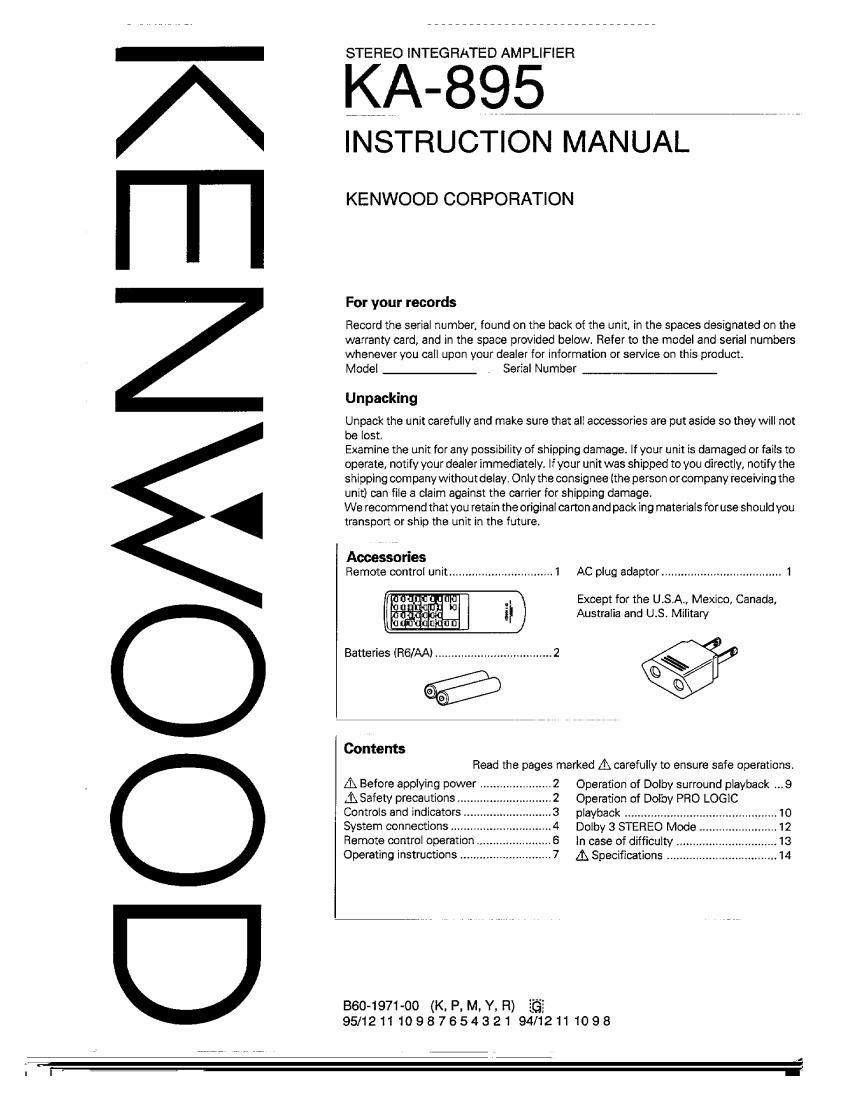
Kenwood KA 895 Owners Manual

This is the 16 pages manual for Kenwood KA 895 Owners Manual.
Read or download the pdf for free. If you want to contribute, please mail your pdfs to info@audioservicemanuals.com.

Page: 1 / 16
left right
Kenwood KA 895 Owners Manual

Extracted text from Kenwood KA 895 Owners Manual (Ocr-read)


Page 1

IOOMN3>I

STEREO INTEGRATED AMPLIFIER

KA-895

INSTRUCTION MANUAL

KENWOOD CORPORATION

For your records

Record the serial number. found on the back of the unit, in the spaces designated on the
warranty card, and in the space provided below. Refer to the model and serial numbers
whenever you call upon your dealer for Information or service on this product.

Model Serial Number

Unpacking

Unpack the unit carefully and make sure that all accessories are put aside so they will not
be lost.

Examine the unit for any possibility of shipping damage. If your unit is damaged or fails to
operate, notify your dealer immediately. If your unit was shipped to you directly, notify the
shipping com pa ny withoutdelay. Only the conSignee (the person orcompany receiving the
unit) can file a claim against the carrier for shipping damage.

We recommend that you retain the original carton and pack ing materials for use should you
transport or ship the unit in the future.

Accessories
Remote control unit.

AC plug adaptor ..................................... 1

Except for the USA, MeXico, Canada,
Australia and U.S. Military

Batteries (R6/AA) .................................... 2

a?

Contents
Read the pages marked A carefully to ensure safe operations.

LB Before applying power .
A Safety precautions ..
Controls and indicators
System connections
Remote control operation
Operating instructions .

\rmewhn

B60-1971-OO (K. P, M, Y, R)

Operation of Dolby surround playback ...9
Operation of Dolby PRO LOGIC

playback
Dolby 3 STEREO Mode
In case of difficulty ..
A Specifications .

95/12111098765432194/12111098

ll)

Page 2

slzecial features A Caution: Read thls page carefully to ensure safe operation.

DOLBY SURROUND PRO LOGIC :This function allows to enjoy a similar Dolby Surround effect to movie theaters from video
software programs carrying the D_ mark.

DOLBY 3 STEREO :The Dolby 3 STEREO provides an active center channel to produce a better, stable center
image. This mode can be used when listening to stereo video program and music or when
surround listening or surround system set-up is not possible.

Remote control unit : The remote control unit is provided with this unit.

Before applying power

Units are dosi nod for n oration: as follows. _
a p *Ac voltage selection

U.S.A. and Canada .
Australia

AC 120 V only . _
AC 240 V only This unit operates on 1 10- 1 20/220/230- 240 volts AC. The AC

AC 230 V only voltage selector switch on the rear panel is set to the voltage
Other countries ' C110-120I220I230-240 V switchable that prevails In the area to which the unit is shipped. Before
connecting the power cord to your AC outlet make sure that
the setting position of this switch matches your line voltage.
If not, it must be set to your voltage in accordance with the
For the United Kingdom following direction,

Factory fitted moulded mains plug Ac voltage selector switch

1. The mains plu contains a fuse. For replacement, use only
a 13-Amp A A-approved (B81362) fuse.

2, The fuse cover must be refitted when replacing the fuse in
moulded plug.

3. Do not cut off the mains plug from this equipment. If the
plug fitted Is not suitable fort a power points in your home M
or the cable Is too short to reach a power p01 nt then obtain
an appropriated safety approved extension lead or adaptor
Ol' consu t YOUI dlea er.

If nonethelessthe mains plug Is cutoff, remove the fuse and
dispose of the plug immediately, to avoid a possible shock
hazard by inadvertent connection to the mains supply. Move switch lever to match your line voltage with

IMPORTANT a small screwdriver or other pointed toolt

The wires in the mains lead are coloured in accordance with
the following code: Blue: Neutral


wrun-Imv- mm- Acm-

Note:
Ourwa rranty does not cover damage caused by excessive line

Brown: Live . . ,
Do not connect those leads tothe earth terminal ofa three-pin voltage due 0 Improper setting 0f the AC voltage selector
plug. switch.
Safety precautions

WARNING:TO PREVENT FIRE OR ELECTRIC SHOCK, DO NOT EXPOSE THIS APPLIANCE
TO RAIN OR MOISTURE.

C-UTION CAUTION: TO REDUCE THE RISK OF ELECTRIC SHOCK. DO NOT
RISKOFELECTRIESHUCK REMOVE COVER (OR BACK). NO USER-SERVICEABLE PARTS
DDNDTOPEH INSIDE, REFER SERVICING TO QUALIFIED SERVICE PERSONNEL.

THE LIGHTNING FLASH WITH ARROWHEAD SYMBOL. WITHIN AN EOUILATERAL
TRIANGLE, IS INTENDEDTO ALERTTHE USER TO THE PRESENCE OF UNINSULATED
DANGEROUS VOLTAGE" WITHIN THE PRODUCT'S ENCLOSURE THAT MAY BE OF
SUFFICIENT MAGNITUDE TO CONSTITUTE A RISK OF ELECTRIC SHOCK TO
PERSONS.

THE EXCLAMATION POINT WITHIN AN EQUILATERAL TRIANGLE IS INTENDED TO
ALERT THE USER TO THE PRESENCE OF IMPORTANT OPERATING AND
MAINTENANCE lSERVICING) INSTRUCTIONS IN THE LITERATURE ACCOMPANYING
THE APPLIANCE.

2 mass (En)

Page 3

Controls and indicators

Inflormation display ,
Dolby SURROUND indicator LOUDNESS 'd'ca So:g§l§§hfi;g§§§}°'f
in ormation
Dolby 3 STEREO Iridlcator DOLBY 3 erREo information

LINE STFlAIG HT indicator
MUTING indicator

filii fiiflfi ddfihfifidfid «it

Volume indicator ---------------------------- SPEAKERS indicator

Remote sensor

Tone controls STANDBY indicator VOLUME CONTROL knob
KENWOOD VOLUME moo.
mm A W n-ia

an M @2- .LJ

l l I Y I
- - ii
- n . . . . .
7| a. 4 a. i...- m.
mom-mm
mu m m m. mum. .mm. m
C3 co ©-© c» FL) r-) G 0mm
mm
\ I
POWER key CENTER SPEAKERS k
PHONES jack BALANCE conml MPDtEr CENTER DELAY TIME kW (+4 -) ey
59 9° ° LEVEL key
LOUDNESS key BYPASS key (+. _, [FE/Ag L_)EVEL INPUT SELECTOR knob
DOLBY 3 STERVEO key LINE STRAIGHT key V '
DOLBY PRO LOGIC key TEST TONE key
Lououess key SPEAKERS key i
Human ears are less sensitive to low frequencies when OFF: This position silences all speakers to permit private use
listening at low volume levels. When the VOLUME CONTROL of headphones. (Speakers indicator goes off)
is set to 810W POSifioni press the LOUDNESS key 10 b0051 the ON: Activates the speakers connected to SPEAKERS
low frequencies. terminals on the rear panel (Speakers indicator lights.)

STANDBY mode of POWER key

When the power cord of this system is plugged into an AC outlet, the STANDBY indicator lights up regardless of the ON/OFF
setting ofthe POWER switch. This indicates that a small amount of current is being supplied to the unit to back up the memory
contents. This mode is referred to as the Standby model While the STANDBY indicator is lit, the power of the system can be
switched ON/OFF from the remote control unit.

mass (Enl 3

h%

Page 15

For CANADA

DOC REGULATION
This digital apparatus does not exceed the CLASS B limits for radio noise emissions from digital apparatus as set out in the rad
interference regulations of the Canadian Department of Communications."

For the U. S. A.

FCC WARNING:

This equipment may generate or use radio frequency energy. Changes or modifications to this equipment may cause harm
interference unless the modifications are expressly approved in the instruction manual. The user could lose the authority i
operate this equipment if an unauthorized change or modification is made.

NOTE:

This equipment has been tested and found to comply with the limits fora Class B digital device, pursuant to Part 15 of the FC
Rules. These limits are designed to provide reasonable protection against harmful interference in a residential installation. Th
equipment may cause harmful interference to radio communications, if it is not installed and used in accordance With th
instructions. However, there is no guarantee that interference will not occur in a particular installation. If this equipment do:
cause harmful interference to radio or television reception, which can be determined by tuning the equipment off and on, th
user is encouraged to try to correct the interference by one or more of the following measures:

- Reorient or relocate the receiving antenna.

- increase the separation between the equipment and receiver.

- Connect the equipment into an outlet on a circuit different from that to which the receiver is connected.

-- Consult the dealer or an experienced radio/TV technician for help.