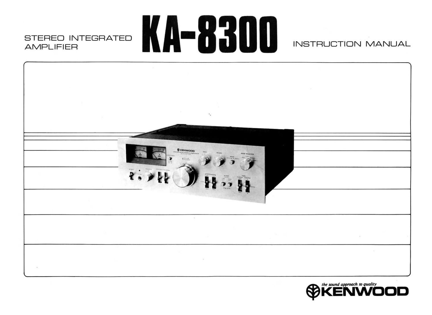
Kenwood KA 8300 Owners Manual

This is the 12 pages manual for Kenwood KA 8300 Owners Manual.
Read or download the pdf for free. If you want to contribute, please mail your pdfs to info@audioservicemanuals.com.

Page: 1 / 12
left right
Kenwood KA 8300 Owners Manual

Extracted text from Kenwood KA 8300 Owners Manual (Ocr-read)


Page 2

INTRODUCTION

Thank you for purchasing our amplifier. Because we take great pride
in the long tradition of quality components, the name Kenwood repre-
sents, your purchase of a Kenwood amplifier places you in a distinguish-
ed family of connoisseurs of superb high-fidelity sound reproduction.

The purpose of this manual is to acquaint you with the operating
features of your new amplifier. You will notice that in every detail of
planning, engineering, styling, operating convenience, and adaptability,
we have sought to anticipate your needs and desires.

We suggest that you read this manual carefully. Knowing how
to set up your amplifier, to the best advantage, will enhance your
listening pleasure right from the start. You will also become aware of
the ease with which you can adjust your amplifier to meet your special
requirements.

Turn the pages and become acquainted with the exciting features
of your new amplifier features that will remain new for endless hours
of listening pleasure.

MAINTENANCE

CONCERNING TRANSISTORS

Transistors differ fundamentally from radio vacuum tubes and

requires special attention to ensure their full performance capabilities.

Given proper care, transistors will provide years of practically trouble-
free performance.

(a) Avoid locations subject to direct sunlight.

(b) Avoid high or low temperature extremes.

(0) Keep the amplifier away from heat radiating sources.

PROTECTION CIRCUIT

The newly developed protection circuit is completely effective
and prevents damage which may be caused by short-circuiting at the
speaker terminals or the power output circuit of the amplifier. When a
short-circuit occurs, this protection circuit will function automatically
to protect the Power Darlington Block. If the Power Darlington Block
fails, this protection circuit will function automatically to protect the
speakers.

NOTES

Units shipped to the U.S.A. and CANADA are designed
to be operated with 120 volts AC only. Units shipped
to the Scandinavian countries are designed to be operated
with 220 volts AC only. Therefore the above units are
not equipped with an AC Voltage Selector Switch so all
reference to such a switch throughout this manual should
be disregarded.

Units shipped to all other countries are equipped with
an AC Voltage Selector Switch on the rear panel that
is preset at the factory to the voltage generally ayailable
in the destination area.

It is very important, however, to check the Voltage Selec-
tor Switch setting and make sure that it corresponds to
your line voltage before connection the power cord into
an AC outlet. If the Voltage Selector Switch requires
resetting, follow the directions outlined on page 7.

CONTENTS
FEATURES ............................... 3
INTERCONNECTING DIAGRAM ................. 4
CONNECTING INSTRUCTIONS .................. 5
CONTROLS AND THEIR FUNCTIONS ............ 8
OPERATING INSTRUCTIONS .................. 10
TROUBLE SHOOTING ........................ 12

Page 10

OPERATING INSTRUCTIONS

PHONO OPERATION

1. Two pairs of phono input jacks, PHONO 1 and PHONO 2, are
provided to enable connections to two turntables. To reproduce
the output of the turntable that is connected to PHONO 1 jacks,
set the INPUT SELECTOR switch to PHONO 1. To reproduce
the output of the turntable that is connected to PHONO 2 jacks,
set the INPUT SELECTOR switch to PHONO 2.

2. Set the MODE switch to STEREO (OFF) and the TAPE (DUB-

BING) switch, TAPE (MONITOR) switch to SOURCE.

Adjust the VOLUME to the desired listening level.

Use the BASS, TREBLE, FILTER, LOUDNESS and PRESENCE

controls to adjust the sound to your preference and to the acous-

tic conditions of your room.

P90

TAPE DECK OPERATION

TAPE MONITORING
If you use the amplifier with 3-head type tape decks, you can

check the sound quality of the recording that is being made by momen-

tarily comparing the recorded signal with the source signal as follows:
Set the TAPE (MONITOR) switch to A (or B) to monitor the recorded
sound. Set the TAPE (MONITOR) switch to SOURCE to monitor the

source signal before it is recorded.

WHEN RECORDING WITH ONE TAPE DECK
Connect the tape deck to either the TAPE A jacks or TAPE B

jacks on the rear panel.

Recording
1. Set the INPUT SELECTOR switch to the desired program source.

Set the TAPE (MONITOR) switch to A or B, whichever side the
tape deck is connected.
2. Recording level should be adjusted with the volume control of

your tape deck.
3. Recording is not affected by the VOLUME, BASS, TREBLE, FIL-

TER, LOUDNESS, PRESENCE, etc., controls of the amplifier.

10

WHEN RECORDING WITH TWO TAPE DECKS

Connect one tape deck to TAPE A jacks and the other to TAPE
B jacks on the rear panel.

Recording

1. Set the INPUT SELECTOR switch to the desired program source.
Set the TAPE (MONITOR, DUBBING) switch to SOURCE.

3. Recordings can now be made into both tape decks simultaneously.
To monitor these recordings, use the TAPE (MONITOR) switch
as follows: Set it to A to monitor the recording being made with
the tape deck connected to TAPE A jacks. Set it to B to monitor
the recording being made in the tape deck connected to TAPE B
jacks.

4. Recording levels should be adjusted exactly as described previously
for single tape deck operation.

Playback

1. The INPUT SELECTOR switch can be at any position.

2. Set the TAPE (MONITOR) switch to the corresponding position
(A or B).

3. Adjust volume and tonal quality.

Dubbing

Tape recordings may be easily duplicated from one tape deck to
another with minimal loss of quality by setting the TAPE (DUBBING)
switch to (A > B) or (B > A) as follows:

1. The INPUT SELECTOR switch can be at any position.
2. Set the TAPE (DUBBING) switch to (A > B) when it is desired to
copy recorded material on the tape deck A for re-recording on the

tape deck B.

Set the TAPE (DUBBING) switch to (B > A) when it is desired to

copy a recording on the tape deck B for re-recording on the tape

deck A. The recording can be monitored.
3. Operate both tape decks simultaneously.