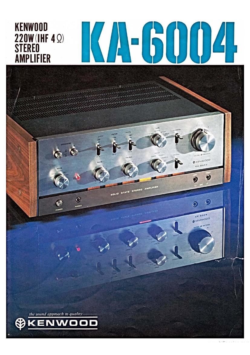
Kenwood KA 6004 Brochure

This is the 5 pages manual for Kenwood KA 6004 Brochure.
Read or download the pdf for free. If you want to contribute, please mail your pdfs to info@audioservicemanuals.com.

Page: 1 / 5
left right
Kenwood KA 6004 Brochure

Extracted text from Kenwood KA 6004 Brochure (Ocr-read)


Page 2

Exceptional Stability of Amplification achieved

Constant Current Driving System

The Kit-6004 achieves an overall high level of
reliability in every performance phase. If only
the strictest requirements are met by each
component, then they are included in the full
assembly potential of this outstandingly unique
amplifier. For example. the preamplifier usesa
new type of can seal (metal cased) transistor
which Is capable of off-setting usual characterv
istlc deterioration in signal-to-noisa ratio
resulting from humidity and temperature wear.
Low noise PNP transistors have been attached
to the top of the equalizer circuit. Also,
super-hiw nichrome evaporated metal film
resistors have been used in the feedback circuit
in the equalizer stage. Each error thus occurs
only within 1 1%. These same resistors are also
equipped in all other significant circuits to
vastly improve SIM and block SIN age
deterioration.

Linear Freuuency Power Output Kept 40W in
20H: to 20KH1.

KENWOOD has been improved in output
indication. In the conventional way, output was
indicated in iust one point of 1KHz. However,
in KENWOOD's latest way of improving
over-all quality guaranteed output is indicated
in the entire range of audio frequency of 20Hz
to 20KHz, Le. the output is indicated in
minimum point", but not in maximum
point".

The maximum output is a performance figure
that implies the dynamic range of the power
amplifier, therefore, only the outputof 1KHz
will imply the imperfect performance of the
amplifier because the output of any amplifier is
usually best near 1KHz. However, as described
in the preceding, KA-SOOd has the circuits to
allow the simultaneous indication of entire
performance. With an all stages direct-coupled
circuit provided, the output linearity in low
pass will be shown by power output data.

putput Power Characteristics
t

«ma-mm

r 1 .............
\a 4

o Pure-complementary Clrcuit o Constant
Current Driving

The KA-6004 employs KENWOOD's exclusive
Constant Current Driving system in the
puracomplementary and direct coupling driver
stage. The highest stability in the amplification
is now obtainable. By minimizing crossover
distortion and by improving phase character-
istics, the Kit-6004 guarantees superb perform
ance quality from ultra low range to far above
the limit of audio frequency. It also prevents
performance from deterioration caused by the
deviation in power voltage. KENWOOD has
overcome the last problem-instability-
remaining in direct coupling amplification. The
refined reproductiOn is fully enjoyable.

9-minute

Higher Reliability Achieved bv Strictly Selected
Components

The pre-emplifier employs a new type of can
seal (metal cased) transistors that are capable of
precluding the characteristic changes, i.e. the
characteristic deterioration of SIN caused by
humidity and temperature. At the top of
equalizer circuit, low noise type PNP transistors
are equipped.

The feedback circuit in the equalizer stage
employs super-high precision nichrome evapo-
rated metal fiilm resistors, each error within
11%. The nichrome evaporated metal film
resistors are equipped in all other important
circuits to prominently improve SIM and
preclude age deterioration of S/N.

,-®\
I

l
,/ "D

0 Protection Circuit

All stages direct-coupled circuit in KA-6004
includes constant current driver circuit capable
of amplifying from DC. The driving way will
amplify faithfully the superlow pass, i.e. plus
minus several Hz of the frequency picked up by
cartridge on bowed record plate and wow-
fluttered turn table, thus the faithful amplifim-
tion will permit unnecessary critical load on
speaker. In addition, if direct current input
should be applied, burning of voice coil may be
caused. To prevent the preceding troubles in
KA-6004, e protecting circuit is employed to
cut superlow pass of 10H: or less in order to
protect speaker against overload.

11 11-

now