Kenwood KA 35 Service Manual

This is the 8 pages manual for Kenwood KA 35 Service Manual.
Read or download the pdf for free. If you want to contribute, please mail your pdfs to info@audioservicemanuals.com.

Page: 1 / 8
left right
Kenwood KA 35 Service Manual

Extracted text from Kenwood KA 35 Service Manual (Ocr-read)


Page 1

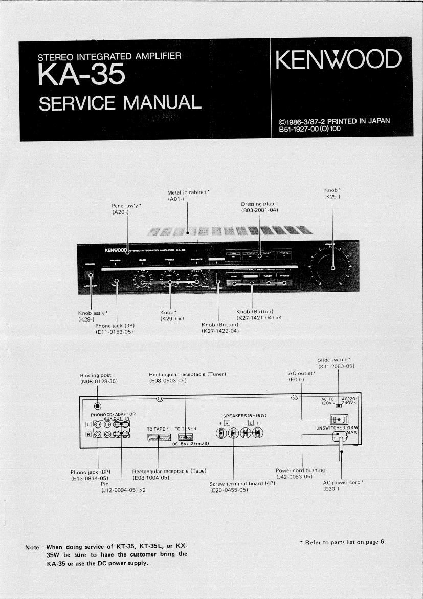
ERERKT§RED AMPLIFIEl? . _ KE NWOO D

SERVICE MAN AL

©1986-3/87-2 PRINTED IN
351-1927-00 (Q) 100

Metallic cabme! Knob'
(AOL) (K297)
Panel assy Dressrng plate
(A20) (BO372081-04l

Knob assy Knob Knub (Bunonl
(K29) (K29) X3 (K277142104) x4
Phone Jack (BFl Knob (Button)
(Ell-0153705l (K274422704)
Slrdc swurclfi
($319083 OJl
Brndmg post Rectangular receptacle (Tunerl AC ourlm
(NOB-012865! (E08r0503705) (E037)
9/ O ACllOr Aczzor
© 120v~$240v~
PHOEgEEfiEEOR SPEAKERSIB-lsnl
m©©®®1 arr» a
| | To TAPE 1 T0 T NER UNSWlTCHED 20m!
E L @_Q9% m m M
m _-. -:1 J
De lav: l2(rm/Sl
Phone jack (8P) Rectangular receptacle (Tape) Power cord bushrnq
(E1370814705l (31841004705) (.1410083705l
P' Screw terminal board (4P) AC power cord
110094705? (520045505) (E307)

Note : When doing service of KT-35, KT-35L, or KX- * Refer 0 parts 51 on page 5

35W be sure to have the customer bring the
KA-35 or use the DC power supply.

Page 2

KA-35
DISASSEMBLY FOR REPAIR

DISASSEMBLY FOR REPAlR

1 Remove 8 screws from the metallic cabinet and lift the
meialllc cabmet up and slide it rearward (o , a).
(Note) Be aware mat the metallic cabine is hooked to
(he projections on the panel. 0

ea,

2, Remove 1 screw and [W0 push rivets at the bottom of
lhe panel (a l and 7 screws at the rear panel (0 ).

3. Remove 1 screw retaining the phone jack pcb (e ).

4. Push the pawls at bolh sides of the panel and release
from lhe hole ( e l.

5 Remove 1 screw at the pcb ( o )

6. The panel with pc boards attached, can be pulled frontr

wardle )V