Kenwood KA 3300 D Service Manual

This is the 38 pages manual for Kenwood KA 3300 D Service Manual.
Read or download the pdf for free. If you want to contribute, please mail your pdfs to info@audioservicemanuals.com.

Page: 1 / 38
left right
Kenwood KA 3300 D Service Manual

Extracted text from Kenwood KA 3300 D Service Manual (Ocr-read)


Page 1

gINTEGRATED AMPLIFIER

-3300D

SERVICE MANUAL

987-4 PRINTED IN JAPAN
851-3150-OO(T)2347

'7 r '
Q (1 l 3%
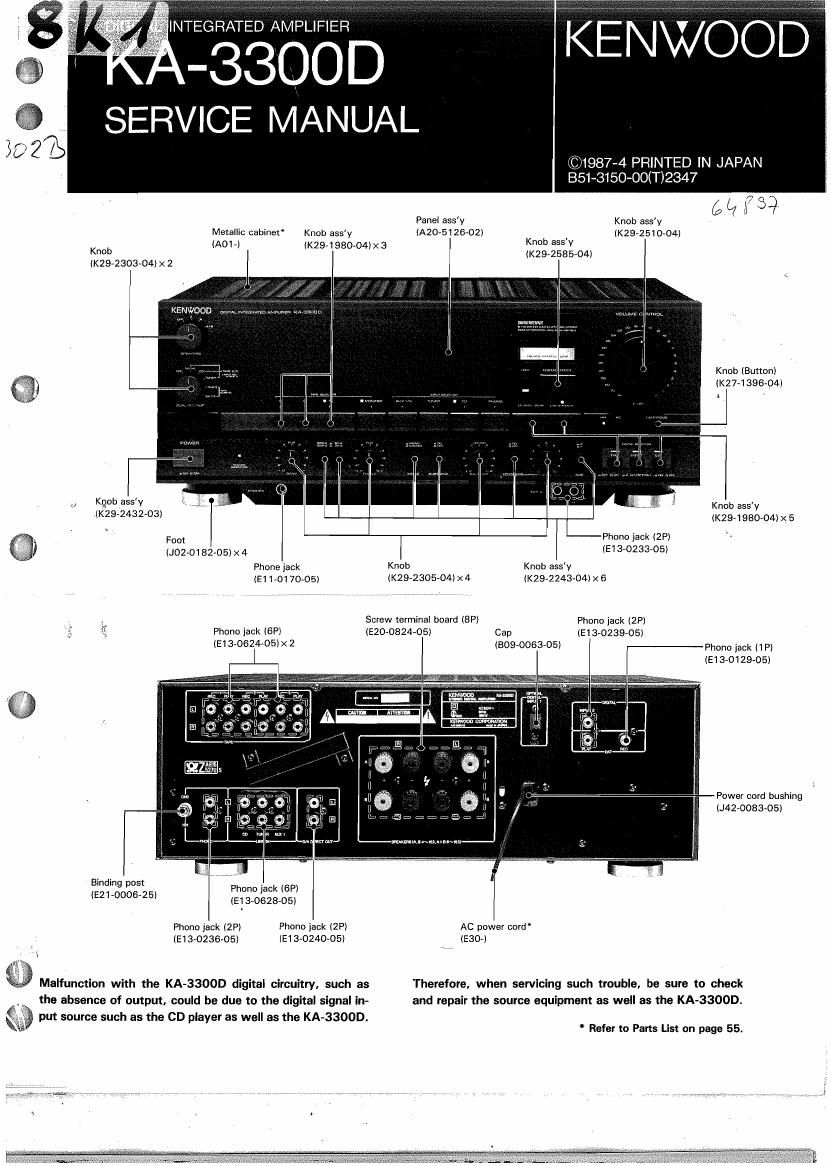
Panel ass'y Knob ass'y
Metallic cabinet Knob ass'y lAZO-5126<02l (K29-2510-04)

(AOL) (K29-1980-04lx 3 Km aSS'Y
(Km-258504)

Knob
(K294301304) x 2

Knob (Button)
(K27-1396-04]

t

Knob assy

Knob assv
(K29A1980704l X 5

.(K29-2432»03)

I Phono jack l2Pi

Foot

(Joz-m 32-05) x4 (5134123305)
Phone jack Knob Knob ass'y
(E1 101 70-06) (K292230504) X 4 (K29-2243-04l X 6
_ Screw terminal board (8P) Phanu jack (2P)
Phono jack (SP) (900824-05) Cap (513-0239-05)

(E13-O624-05lx 2 (8090063705) Phonu jack (1 P)
(930129-05)

Power cord bushing

(J42v0083-05)
,......M.t...~..u
Binding post . R
Phone jack lGP)
(521'000625 (E1 3-0628-05)
Phonojack (2P) Phone jack (2?) AC power cord"
1513-0236435) lE13-0240-05) lE30»)
Maliunction with the KAv33OOD digital circuitry, such as Therefore, when servicing such trouble, he sure to check
the absence of output. could be due to the digital signal in» and repair the source equipment as well as the KA-33OOD.

E put source such as the CD player as well as the KAv33OOD.
* Rsfer to Parts List on page 55,

Page 2

DISASSEMBLY FOR REPAIR.
BLOCK & LEVEL DIAGRAM
CIRCUlT DESCRIPTION ....................
ADJUSTMENT/REGLAGES/ABGLEICH ..

VOLTAGE TABLE ................................................. 30

#9?

CONTENTS

PC BOARD ..............
ClRCUlT DlAGRAM.,,.
EXPLODED VIEW

PARTS'ILlST .......... n55
SPECIFICATIONS .......................................... Back Cover

DISASSEMBLY FUR REPAIR

REMOVING THE FRONT PANEL AND CON-
TROL UNIT

. Remove the six screws fixing the metallic cabinet to the
chassis (left side: 3, right side: 3) to).
. Remove the two screws attached to the metallic cabinet

(0).

. Remove the metallic cabinet by lifting it in the direction of
the arrow (9).

. Remove the seven screws attached to the front panel
(0),

. Remove the seven knobs from the front panel. Also
remove the seven nuts taking care not to damage the
front panel (9).

. Loosen the four screws insert into the two couplings
(No.19 in the enlarged diagram) (9).


\I

10.

11.

12.

. Remove the front panel in the direction of the arrow (0).
. When attaching the front panel again, align the grooves

the front panel with those of the extension shaft. If this
has not been done, the panel cannot be attached cor-

rectly l9 ).

. Remove the screw from the metal part in the power

switch section (9).

When attaching the power switch section again, insert
the guide pins of the metal part (two on each part) into
the slots on the frame (front) ( (0 ).

Remove the four screws attaching the connector cover
( m ).

Remove the connector cover in the direction of the arrow

(Q).

13.

14.

15.

16.

l7.

«'9

(a).

DISASSEMBLY FUR REPAIR /

Remove the two screws from the Control Unit
(X1 1-2350-81) (A/7) (@i

Remove the parallel cable which has been connected to
CN7 of the Control Unit (X1 l~ ) (A/7) in the direction of
the arrow (Q).

Remove the parallel cables which have been connected
to CNS and CN4 of the Control Unit (X1 1- ) (AI7) (0).
Crush the heads of two unit holders which attach the
Control Unit (X1 1-) (AH) to the frame (from) using radio
pliers, and pull them out from the Control Unit (@l.
Remove the Control Unit (X11- ) lA/7) in the direction of
the arrow (0).

REMOVING THE BOTTOM PANEL; L

K

2
Remove the four screws from the connector cover to).
Remove the connector cover in the direction of the arrow

(0).

. Loosen the six screws on the bottom panel (9).
. Remove the two screws from the rear side of the bottom

pahel (9).
Remove the two screws from the AUX connector section

(0).

Remove the two screws from the PHONES jack section

7, insert the AUX connector section into the slot on the bot»

tom panel (0).

. Insert the PHONES jack section into the slot on the bot-

tom panel (9).

. Remove the bottom panel from the main chassis in the

direction of the arrow (0).

Attacking THE SIGNAL PROCESSOR

UNITS AND REAR PANEL

. Remove the metallic cabinet and bottom panel before

performing the following operations.

. Disconnect the four connectors which have been con-

nected to the frame (rear and front) (0).

. Remove the 13 screws retaining the shield cover (a).
. Remove the shield cover in the direction of the arrow

(6).

Page 3

\IO)

, Remove the screw retaining the thermal switch, then
remove the thermal switch and its metal fixture i0).

. Lift the shield case upward l6).

. Separate the connector cord from two unit holders at-
tached to the shield case (fl).

. Disconnect the parallel cable from CN1 of the Signal Pro~
cessor Unit:(X32-I 1 12-71) IC/6I (0).

t Lift the two Signal Processor Units (X32- ) (A16, BIG) in
the shield case Upward.

10. Pull out the coupling from the remote switch shaft (9).
11. Remove the eight screws (four from the upper side, four

from the bottom side) from the frame (rear) i ® I.

12. Remove thefour screws from the bottom side of the

frame (rear) ( O I.

9

It

13. Remove the 14 screws from the rear panel I Q I.
14,
I ® I.
15.
sliding the left-hand side upward ( m ).

Disengage the claw fixing the rear panel to the chassis

Remove the rear panel in the direction of the arrow by

DISASSEMBLY FUR REPAIR

l6.

17.

18,

19.

20.

2lt

When attaching the rear panelffollow the procedure and
cautions below. ,

Engage the claw of the rear panel onto the notch on the
chassis ( w I.

Insert the claw of the frame (left) correctly into the slot on
the right side of the rear panel. At this time, the upper
surface of the frame (rear) shall come above the rear

panel i 0 I.
Insert the claw of the chassis into the slot on the frame
(rear) i 0 ),

Pile the Main Amplifier unit reinforcement metal (No.736
in the enlarged diagram), frame (rear), Main Amplifier
Unit iXO7-2320-82) and chassis in this order, and fix
them together using a screw l w ).

Attach the rear panel as shown in the diagram ( ® I.

D/A
OUT

BLOCK & LEVEL DIAGRAM

no
>
at
2
x:
m

m
i:
In
2
<1
In
n.
m

g
2
Q.
a

1

SPEAKER A

/
{ / wiNKING
INDICATOR

a2-

PROTECTION
7 )

IC3
O

RELAV

LIMITTER * DRIVER
ix

033~35
(X074

SEL

W

lNFUTl
(OPTICAL) MODULE

,7

DlGlTAL
lN/OUT

AuXI
AUXZ

m
- 35
N _x
m -<
5 (A?
o m
'- I-
x
m
9 a a
9m
7 Z '25
N m m m-
m an m mJn N
5. in g as _-
m 53 van 5,2 x u
I 0.4 gfi mg _,
m i.
2 f k K
:4:
m L E
X < m -
c? 3 a i; 9
. 't (It:
a E g1 .9
< 3 05 log n! s z ,t
)- U! 1 «<1 nga - 8N
4 .5 7 >33 .0 _, g may
D W 0! o N
to; o ,2 .
:I; m,_ 5 g > ,5
s E 35% r- a 5
.3 ME n §w .
m 40: vro m m m <2.-
5 SE 0 I x ) its >5
_ 5;: n L J *9: 38
a» 5h 9 - m mzo u-
3 T o-wV-{t OJ 2"
ot .1»-
m . . <10
5 gin: eta:
N 88° wee
<- " no
9
<1 N7
g, " fi H
' S 0 E'd
N _ _
E {3 a a5 >§
E 53 a
In -I '3 m z-
o _g m c
r tr 1 Pg
5
El I :22 ,9
3| | 5
:in I I3
9°: I
Bl I
ma
I¥I i
"°I i
03'
do I
«El i
Lg I
Nkl \
in
9§' ' new
on. _____ J ii?
i #735
- r-N' -
.4. I 7 .4
rod >5 | g
X 9
«we I a s 3'
TS'A I (it 1 .33
Pint»? I u: E
SEI Q I
a L: . a
Z w I r:- _,m
3 I"" . 8 <0
3
mg I l i GE
N I Int: o
2% I ' 5, a
U ._..J it
P: , ._ .......
° I.
(I
m
z
D
)-

{-REC
TAPE!

ANALOG
IN/OUT

r-REC

LPLAV

,- REC
TAPE3

Lm @

LPLAv
TAPE?