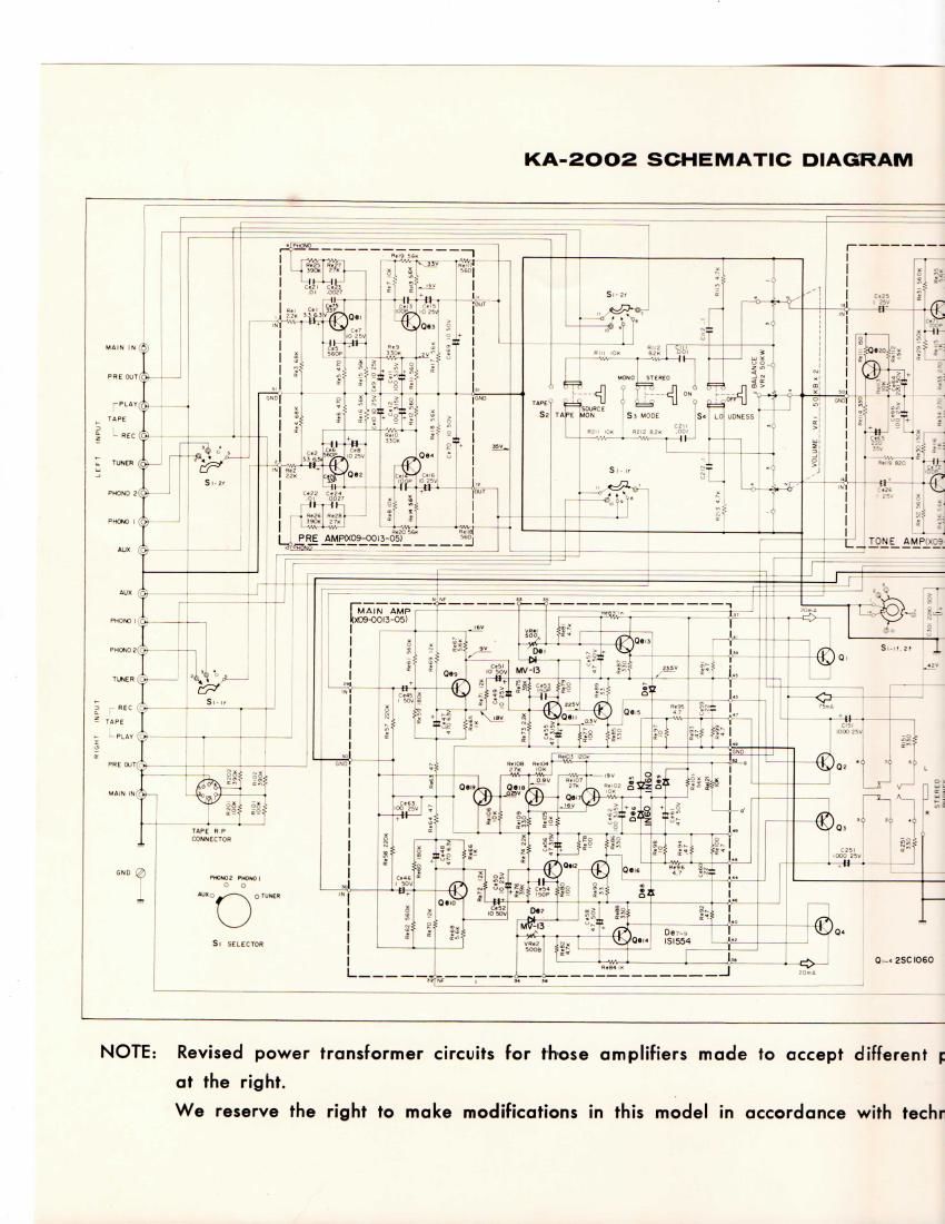
Kenwood KA 2002 Owners Manual Schematic

This is the 18 pages manual for Kenwood KA 2002 Owners Manual Schematic.
Read or download the pdf for free. If you want to contribute, please mail your pdfs to info@audioservicemanuals.com.

Page: 1 / 18
left right
Kenwood KA 2002 Owners Manual Schematic

Extracted text from Kenwood KA 2002 Owners Manual Schematic (Ocr-read)


Page 1

KA-2002 SCHEMATIC DIAGRAM

mam

um

bum m 5

was who} _,

amp, . a

up: 5; Mon:


amine: LEE
2.» .gwyfi 4,,

VPEWE int 45 m {g

\
L

PRE AMPtXOS-OOIB 0
mar - -


M f

» N.
______ .o______
[_MA|N AMP #77 ,
100900505)

MOMMCnv-r


mm zmifi ,-,.

smurf g

mm w,

A ,
up: up
mnnzcmfi
\
7
"9 w mm mm.
a u
1010 mm
w OO
5. smma

Oh: ZSCIOGO

NOTE: Revised power transformer circuits for those amplifiers made to accept different p
at the right.
We reserve the right to make modifications in this model in accordance with techr

Page 4

SPECIAL KA-ZOOZ FEATU RES

1. Wide power band width of 20 Hz to 30,000 Hz with very low lM distortion.

2. 2 dB step type tone controls with BASS and TREB LE.

All transistor amplifier provides wide 20 to 30,000 Hz frequency response and
20 to 30,000 Hz power band width.

High damping factor 50 (8 ohms), for excellent transient response.

Pre-amplifier outputs for use with other power amplifier or multi-channel system.
2 pairs of magnetic phono input jacks for 2 sets of record players.

Push-button controls regulate LOUDNESS Contro|,MODE,TAPE Monitor Switch.
Front panel stereo headphone jack.

573.???

Page 11

TAPE RECORDER CONNECTIONS 8: OPERATIONS

PIN JACK

You may record FM (monaural or stereo), AM broadcasts and LP records by
connecting the output jack of TAPE REC to the input jack of your tape recorder.
Play back your tape recordings by simply connecting the line output of your tape
recorder to the TAPE PLAY jack of your KA'ZOOZ.

RP. CONNECTOR IDIN CONNECTORI

Normally for most recording and playback, separate cables must be connect
ed to their respective input jacks on the amplifier; however. if your tape recorder is
equipped with R 84 P (Record and Playback) 5-Pins connector type patch cord, 3
special jack (connector) is provided on the KA-2002 enabling both recording and
playback with this single cable.

PLAYBACK

Push the POWER switch for power on.

The SELECTOR switch can be at any position.

Push the TAPE MONITOR switch to PLAY.

Sta't the tape recorder.

Adjust the volume. Use the BASS,TREBLE and LOUDNESS to suit your
listening pleasure as explained previously.

5"?pr

TAPE MONITOR

The KA-2002 incorporates a Tape Monitoring circuitry enabling you to
monitor while you record. Connections to the tape recorder are made as explained
in the section dealing with "lnterconnecting Diagram".

For Two-head Tape Recorders

Ordinary two-head type tape recorders are not equipped with a separate
playback monitor amplifier to enable tape recording and simultaneous monitoring.
Therefore. when recording, set the Tape Monitor Switch to SOURCE position,
and feed the signal to be recorded through the KA-2002. And, for playback of the
recorded tape through the KA-2002 speaker system. set TAPE MONITOR switch
to PLAY position.

IO

For Three-had Tape Recorders

Three-head type tape recorders have separate recording and playback heads,
and their respective separate amplifiers. This enables simultaneous playback moni-
toring of the recording. For operating the KA-2002 in conjunction with three-head
type recorders. set the Tape Monitor switch to "PLAY" position. This enables
monitoring the recording and fully controlling level, acoustic balance, microphone
position, etc.

For playback of the recorded tape, set TAPE MONITOR switch to PLAY
position.

TAPE RECOPYING

To make a copy cl 3 recorded tape on to another tape, follow the connecting
instruction as shown in Figure 6.
1. Push the POWER switch for power on.
2. Set the SELECTOR switch to AUX position.
3. Push the TAPE MONITOR switch to PLAY.
4. Operate your equipments simultaneously.

RECORDING

INPUT

Figue 6. Tape flecopyhg.

Page 13

TROUBLE SHOOTING

In initially installing this amplifier improper connections may remit in one of
the following indications of trouble. Their possible mas and corrective measures
are listed below to facilitate installation.

During Tuner or Phone Operation than Corr-won
No pilot lamp indication, no sound although Poor AC plug connection. Check plug contact.
AC is switched 0N. Blown fuse. Replace fuse. If it blows again. trouble must be

corrected.

No sound from LEFT and RIGHT.

Sound only from one side.

Speaker cords disconnected.
Volume Control at 0 (extreme left)
TAPE MON switch at PLAY position.

PRE MAIN SEPARATE SWITCH at
SEPARATE Position.

Poor speaker cord connections.
BALANCE control set to one extreme or other.

Check connections from amp output to speakers.

Set to appropriate volume level.

Always set to SOURCE except when using tape
recorders.

Always NORMAL position except when using to-
gether with multi-channal or 3-0 systems.

Check amp output and speakers connections.
Adjust BALANCE control.

Noise when AC is switched ON or when
volume is adjusted immediately after.

unbalance results when volume is lowered.

Intermittent speaker response at 3 second
intervals.

Difference in volume level of radio and phono.

Darin] Phone Operation Only

No sound from LEFTand RIGHT, or sound only
from one side.

Loud hum drowns outisound.

Sound audible but backgrournl hum occurs.

Sound audible but continuous background buzz
interferes.

Insufficient circuit warmup.

iLEFT RIGHT resistor values unbalanced.

Allow 5 - 6 second interval after switching AC 0N.
before manipulating volume control.

Adjust BA LANCE control.

Protection Circuit indication of short circuit in
the output.

Difference in received signal and phono output
levels.

Cum
Player output disconnected.

Poor Player output cord prong connections.

Player output cord picking up hum from AC
cord.

Player not grounded.

TV signal picked up by player output cord.
Frequently occurs near TV transmitting anten-
na.

Set to appropriate volumaagl.

Check speaker cord connections.

Correction

See that player output cord is firmly plugged into
amp input.

See that player output cord is firmly plugged into
amp input.

Keep player output cord away from AC cords.
Choose cord paths which keep hum at a minimum.
Twist LEFT RIGHT player output cords together.
Reverse player AC plug connections.

Connect player ground wire to GND terminal.

Route player cord so that buzz is minimized.

Howling noise occurs when volume is raised or
bass response is increased.

Speaker vibrations induce feedback in pickup.

I2

Increase distance between player and speakers.
Choose speaker locations carefully. Remember. loose
flooring induces howling.

Page 15

MOUNTING TEMPLATE

1,.3

?;,/ beg-H--e~¥4lzg";trsf'rfafl
, / x /
4 3 g-g PANEL CUTOUT

SIDE VIEW

,m . _ at.

LOC TIONS 0F FASTENING
HOLES FOR INSTALLATION

II»

. 3;
SUPPORTING SHELF

...1
JWING NUT &- WASHER

DIRECTIONS FOR PANEL MOUNTING

Locate the supporting shelf at the height you wish the ampli-
fier positioned.

Remove the four bottom legs.

An air space must be made between the bottom of the set and
the supporting shelf to assure good ventilation and cool
operation. This space an be made by placing two boards
which measure 9/16" thick by 1" to 2" width between ohasis
and the supporting shelf.

Make a panel cutout in the size shown at left, 313/l6" x
12-5/8". The bottom of the cutout should be flush with the
bottom plate oi the amplifier, as shown in the side view. The
distance between the bottom of the cutout and the top of the
supporting shelf is 9/16".

The amplifier is held in place by two bolts. The holes must be
made in the shelf to correspond with the holes in the amplifier.
Use the "Top View template to lomte these holes on the
supporting shelf. The holes should be made 1/4" in diameter
or somewhat larger.